
Showing posts with label video. Show all posts
Showing posts with label video. Show all posts
Tuesday, February 19, 2013
Temperature Sensor, Frame Design and News
Last post I said I would get my thermistor temperature sensor working by the next post (ie this one). I have it working but its not calibrated and thus gives the temperature a few degrees out.


Saturday, January 26, 2013
Stepper Demo and Serial LCD
I have finally got my Stepper motor demo program working. As well as the problems in the last post there were a couple others. The first one of these was that I was trying to add a signed integer to an unsigned one. I fixed this which then made me realise I would have to change the number of steps for reversing from -1 and -2 to 7 and 6 respectively. This wasn't so bad but I then found that the motor was going quite slow compared to the test program. This stumped me for a while until it came to me that unsigned 8bit integer, is just that 8 bit not 8 numbers in total (4bit). So I put in an if statement that stated if the counter position was greater than 7 to remove 8 from it so to get back into the correct range of 0-7. I won't post the code in this post as I still need to tidy it up and comment it. Here is another video of the stepper motor, this time running the demo code. Basically it moves 45 degrees forward, 45 degrees back, then flashes a light (not shown) and then starts alternating going backwards and forwards 360 degrees.
The video is slightly better quality today as I took this on my camera rather than my phone. Same goes with the pictures further down the post.
So after getting the stepper motor finally working, I decided I would start on the LCD display but this time using serial communication. This started fairly well and had a good example in the manual for the chip. There was also a tutorial on AVR Freaks that helped. So I wrote all this up and sent it to the microcontroller and it started writing to the screen, the only problem was that it wasn't writing what it should have. This looked like the next picture, which looks like asian symbols but I think are just normal symbols that are part of the extended ascii sequence.
 At I gave up programming and did some research before bed. I found another forum topic on AVR Freaks about UART corruption which is what I thought was happening. These posts indicated that it was most likely to do with the baud prescaller number calculated in the code. The next morning I tried moving around the number given in the manual for 8Mhz but no such luck. I had been seeming to get better results from lower numbers so I decided to try the number for 4Mhz which worked. I have no idea why it is running at 4Mhz as the fuses in AVR Studio say its running from a 8Mhz clock and not divided by 8 but there may be something I'm missing.
After fixing the communication I was finally able to turn on the back light of the LCD03-20x4. Next I managed to get some text written to the screen. With the help of this set of posts, again on AVR Freaks, I set up stdout for C to be the LCD screen and so printf now prints directly to the LCD.
 I'll post the code for what I have done with the screen below. I would do a circuit schematic but really its quite obvious for the ATmega88a as there is only one UART module and so there is only one TX and one RX pin on the chip. I'm also quite tired tonight after redoing the roof on part of our house (doing the same tomorrow), so can't think what else I was going to post.
The code really should be commented but I'm too tired to do so now and I'll most likely update and clean up the code soon so I can post it after that. Next job I'm thinking I'll do is to get SPI working between two chips. Before I do this though, I need to get the chip to run without the need for the programmer (AVR ISP mkII) being plugged in.
So after getting the stepper motor finally working, I decided I would start on the LCD display but this time using serial communication. This started fairly well and had a good example in the manual for the chip. There was also a tutorial on AVR Freaks that helped. So I wrote all this up and sent it to the microcontroller and it started writing to the screen, the only problem was that it wasn't writing what it should have. This looked like the next picture, which looks like asian symbols but I think are just normal symbols that are part of the extended ascii sequence.

After fixing the communication I was finally able to turn on the back light of the LCD03-20x4. Next I managed to get some text written to the screen. With the help of this set of posts, again on AVR Freaks, I set up stdout for C to be the LCD screen and so printf now prints directly to the LCD.

 #define BAUD_PRESCALE 51 // Started at 103 , down to 95, upto 112
 #define USART_LCD_MAXLINES 4
 #define USART_LCD_CHARS 20

 #include <avr/io.h>
 #include <util/delay.h>        // for _delay_ms()
 #include <stdio.h>
 #include <stdint.h>
 #include <ctype.h>

 void USART_Init (unsigned int ubrr)
 {
      /* baud rate */
      UBRR0H = (unsigned char) (ubrr>>8);
      UBRR0L = (unsigned char)ubrr;
      /* Enable receiver and transmitter */
      //UCSR0B = (1<<RXEN0)|(1<<TXEN0);
      UCSR0B = (1<<TXEN0);
      /* Set frame format: 8bit data, 2 stop bit */
      UCSR0C = (1<<USBS0)|(1<<UCSZ00)|(1<<UCSZ01);
 }

 void USART_Transmit (unsigned char data)
 {
      /* Wait for empty transmit buffer */
      while (!(UCSR0A & (1<<UDRE0)))
           ;
      /* Put data into buffer, sends the data */
      UDR0 = data;
 }
 int USART_PrintChar (char character, FILE *stream)
 {
      USART_Transmit (character);
      return 0;
 }
 FILE uart_str = FDEV_SETUP_STREAM(USART_PrintChar, NULL, _FDEV_SETUP_RW);

 void USART_Print_Location(uint8_t line, uint8_t pos) {
      if ((line < 1) || (line > USART_LCD_MAXLINES)) {
           line = 1;
      }
      if ((pos < 1) || (pos > USART_LCD_CHARS)) {
           pos = 1;
      }
      USART_Transmit(3);
      USART_Transmit(line);
      USART_Transmit(pos);
 }

 int main(void)
 {
      USART_Init(BAUD_PRESCALE);
      stdout = &uart_str;
      unsigned char sendChar = 65;
      USART_Transmit(19);
      USART_Transmit(12);
      USART_Print_Location(1,5);
      printf("Hello World");
      USART_Print_Location(2,9);
      printf("from");
      USART_Print_Location(3,1);
      printf("RichRobo on Blogger");
      while(1)
   {
     //TODO:: Please write your application code
   }
 }
The code really should be commented but I'm too tired to do so now and I'll most likely update and clean up the code soon so I can post it after that. Next job I'm thinking I'll do is to get SPI working between two chips. Before I do this though, I need to get the chip to run without the need for the programmer (AVR ISP mkII) being plugged in.
Tuesday, January 22, 2013
Stepper Motor Setup
Well after getting my stepper motor to work last night with full steps, today I got it to work with half steps and so wrote up the circuit and the major problem I had encountered.
Firstly here is another video of the stepper, this time running at a decent speed, using half steps.
You can't tell from the video, but the motor does run much smoother with half steps as well as being able to run faster (logical if you think about how charging the coils works).
So I'll give the schematic next to show you the circuit layout, then I'll go into the problem I had and finally the code. The schematic does look messy, I would fix this by labelling the wires but I found out tonight that KiCAD doesn't have this functionality so it will have to do.
 In the test program shown working in the video, the LEDs in the bottom right seem like they are on all the time but they are actually connected to each coil of the stepper and so turn on when that coil is on in that direction. This was so I could work out what was happening and can easily be removed. I will go into why they were useful in a second. Other things to note are that the switches on the left are attached but not used in this test program as these were for my original demo program which I will get working soon and so can do more tests. In the video there is a SMD chip on a red board. This is not actually attached to the circuit at the moment. This is because it is the other stepper driver chip (A3982SLB-T) which I will test later when I have a better heat sink for it than the tiny one I bought at the time which doesn't fully cover it.
OK, so my problem for why the stepper wasn't working was quite trivial in the end. It turned out that I had connected the stepper in a non standard way and so the guides on programming for a stepper motor didn't work.
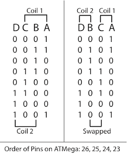 Basically the standard order is connecting the coils in alphabetic order as shown in their data sheets. This means that the coils are intertwined as shown on the left of the above picture. This wasn't how I connected them as it seemed more logical to me to attach them so the coils were attached next to each other as shown on the right. As a side note, the letters in the picture are the letters from the data sheet, the numbers are the logical output of the pins on the pins of the microcontroller, and so when in the wrong order do weird things. This meant that instead of moving, the stepper oscillated between two locations while the rest of the time, the potential difference (voltage) over the coil was zero (ie both off or both on). What I realised from testing with the help of the LEDs connected and using a slower clock speed was that I had one coil with both sides on logical 1 and the other coil on logical 0 most of the time hence why it was not working. So once I swapped the two middle columns of the logical states in the table above, it all magically started working. This was something I had not read in any of the tutorials online or in text books to be careful of so I'm quite happy that I managed to solve this for myself.
So here is my code:
(Note to self, using http://codeformatter.blogspot.com/ with settings 5 spaces per tab, no line numbering, don't remove blank lines, yes to stylesheet, auto height and no to alternative background)
Its fairly rudimentary at the moment and needs tidying up but it shows the gist. I used decimals as it was easier to test and write down than using binary numbers which I had used in my demo which wasn't working. For those interested, binary in GCC and Atmel Studio can be written down using 0b as a prefix to the binary string. The code above won't work straight from copying as I have commented out the method for changing between full steps and half steps. The other thing to note is that my chip is running at 4Mhz so the time would need to be changed if running at a slower speed.
I think that is all about getting the stepper working. Tomorrow I'll either fix it up for use with my demo program which turns certain amounts and then gives control to the buttons, or I'll have a go with serial communication to the LCD screen. I might if I have enough time, have a look at both.
Just to finish off, I was looking around Australian Robotics this afternoon and found there is a ball bearing on there which is 5mm thick with an ID of 5mm and OD of 16mm. This could potentially work for wheels on the carriage but after realising that the motor shaft is also 5mm diameter and is quite large realistically, I think a smaller shaft diameter would make more sense. The same website also has a coupler for converting the 5mm diameter shaft of the motor to 8mm which would work well for M8 threaded rod or an 8mm ball screw.
I'll should have enough stuff to post again by tomorrow night or the night after as will be at home working on it for the next few days. Should be good.
Firstly here is another video of the stepper, this time running at a decent speed, using half steps.
So I'll give the schematic next to show you the circuit layout, then I'll go into the problem I had and finally the code. The schematic does look messy, I would fix this by labelling the wires but I found out tonight that KiCAD doesn't have this functionality so it will have to do.

OK, so my problem for why the stepper wasn't working was quite trivial in the end. It turned out that I had connected the stepper in a non standard way and so the guides on programming for a stepper motor didn't work.

So here is my code:
 #include <avr/io.h>
 #include <util/delay.h>        // for _delay_ms()

 int main(void)
 {
   DDRC |= 0x0F;

      uint8_t curLED = 1;
      while (1) {
           PORTC = curLED;
           _delay_ms(7); // 18 for full steps, 7 for half steps

           /** Full Steps **
           if (curLED == 1) {
                curLED = 4;
           }
           else if (curLED == 4) {
                curLED = 2;
           }
           else if (curLED == 2) {
                curLED = 8;
           }
           else {
                curLED = 1;
           }
           **/
           /** Half Step **
           if (curLED == 1) {
                curLED = 5;
           }
           else if (curLED == 5) {
                curLED = 4;
           }
           else if (curLED == 4) {
                curLED = 6;
           }
           else if (curLED == 6) {
                curLED = 2;
           }
           else if (curLED == 2) {
                curLED = 10;
           }
           else if (curLED == 10) {
                curLED = 8;
           }
           else if (curLED == 8) {
                curLED = 9;
           }
           else {
                curLED = 1;
           }
           */
   }
   return 1;
 }
(Note to self, using http://codeformatter.blogspot.com/ with settings 5 spaces per tab, no line numbering, don't remove blank lines, yes to stylesheet, auto height and no to alternative background)
Its fairly rudimentary at the moment and needs tidying up but it shows the gist. I used decimals as it was easier to test and write down than using binary numbers which I had used in my demo which wasn't working. For those interested, binary in GCC and Atmel Studio can be written down using 0b as a prefix to the binary string. The code above won't work straight from copying as I have commented out the method for changing between full steps and half steps. The other thing to note is that my chip is running at 4Mhz so the time would need to be changed if running at a slower speed.
I think that is all about getting the stepper working. Tomorrow I'll either fix it up for use with my demo program which turns certain amounts and then gives control to the buttons, or I'll have a go with serial communication to the LCD screen. I might if I have enough time, have a look at both.
Just to finish off, I was looking around Australian Robotics this afternoon and found there is a ball bearing on there which is 5mm thick with an ID of 5mm and OD of 16mm. This could potentially work for wheels on the carriage but after realising that the motor shaft is also 5mm diameter and is quite large realistically, I think a smaller shaft diameter would make more sense. The same website also has a coupler for converting the 5mm diameter shaft of the motor to 8mm which would work well for M8 threaded rod or an 8mm ball screw.
I'll should have enough stuff to post again by tomorrow night or the night after as will be at home working on it for the next few days. Should be good.
Monday, January 21, 2013
Stepper Motor Full Step
Very quick post, but tonight I decided I would write a small test program to manage the stepper motor now that I can see which coils are on using LEDs. I was successful in getting the motor to turn which is good as it means the wiring is all correct and it must be my original program that does not work. I'll have a better look into this in the next few days.
This test program, as my first test has very large waiting periods between changing step so the motor does go quite slow. The other thing to note for the test program I'm using is that it is using full steps rather than half or smaller. This is simply because I'm testing and was my first go. I'll do a proper write up later about the circuit and setup but for the time being I have a video showing it moving, as I'm quite happy I've managed to get it working even though its a minor achievement.
This test program, as my first test has very large waiting periods between changing step so the motor does go quite slow. The other thing to note for the test program I'm using is that it is using full steps rather than half or smaller. This is simply because I'm testing and was my first go. I'll do a proper write up later about the circuit and setup but for the time being I have a video showing it moving, as I'm quite happy I've managed to get it working even though its a minor achievement.
Monday, October 8, 2012
3D Printed Optics
Here's an interesting application for 3D printing I came across today. It requires a high resolution to print but otherwise would be quite doable.
Subscribe to:
Posts (Atom)