In this post, I'll talk about some design stages for the Octocopter I'll build. Its a fairly small post as I'm researching how to develop with Eclipse and ARM chips.
Showing posts with label 3d printer. Show all posts
Showing posts with label 3d printer. Show all posts
Thursday, April 25, 2013
Sunday, April 7, 2013
RepRap Funds and Multicopter
Well University has been pretty busy so I haven't been doing much on any projects at home since the last post. I did though, over Easter, have enough time to think up some more ideas. But a few small things before I start on these.

Saturday, March 2, 2013
First week back at uni
So I'm back at uni now and this meant orientation week, so this week I have done next to nothing on the printer as I've been too hungover or catching up with people I haven't seen in a while. There are a few things I have had a look into though.
Friday, February 22, 2013
Frame Design
Over the last few days, I've been having a go in Inventor and doing a mock-up of my designs. (I say mock-up as explained later.) This has helped solved some of the problems I've had and provoked ideas on what needs to be done and changed. None of the pictures have the x slide/axis carriage shown as that is a more detailed feature and so I haven't designed even a basic version yet for the design.
Tuesday, February 19, 2013
Temperature Sensor, Frame Design and News
Last post I said I would get my thermistor temperature sensor working by the next post (ie this one). I have it working but its not calibrated and thus gives the temperature a few degrees out.


Sunday, February 3, 2013
Debugging, Buttons, new purchases
Sorry this post isn't going to have any pictures as its all ideas, or what I have done but not finished yet.
So yesterday I realised I hadn't actually done a project that involved buttons on the AVR. I had done so on the TI LaunchPad which I had used before I got the AVR hence why I thought I had done so (I only swapped 3 months ago). Due to this I have decided I'm going to make another test program which will take the state of four buttons and translate them into a 4 bit binary and display the decimal reading on an LCD screen. As I was getting my breadboard ready for the SPI test, I moved another AVR onto the same breadboard and downloaded the LCD code. Worked so I then started tidying up the code to make it more of a library rather than all in one file. I finally got the code to work (the statements for getting printf to work are quite hard to satisfy) and so downloaded to the AVR and the display did nothing. I thought it must be the code as it seemed to be working on the original chip on the board but not the second. So I spent the next hour trying to troubleshoot the code, eventually going back to the original code that I posted last time and it still didn't work. Eventually I found out that one of the crimped pins within the header plug on one end of the LCD cable had come loose and so the LCD wasn't actually receiving the data! Good lesson to remember - check the hardware first, don't assume its all ok, specially cables.
So yesterday I realised I hadn't actually done a project that involved buttons on the AVR. I had done so on the TI LaunchPad which I had used before I got the AVR hence why I thought I had done so (I only swapped 3 months ago). Due to this I have decided I'm going to make another test program which will take the state of four buttons and translate them into a 4 bit binary and display the decimal reading on an LCD screen. As I was getting my breadboard ready for the SPI test, I moved another AVR onto the same breadboard and downloaded the LCD code. Worked so I then started tidying up the code to make it more of a library rather than all in one file. I finally got the code to work (the statements for getting printf to work are quite hard to satisfy) and so downloaded to the AVR and the display did nothing. I thought it must be the code as it seemed to be working on the original chip on the board but not the second. So I spent the next hour trying to troubleshoot the code, eventually going back to the original code that I posted last time and it still didn't work. Eventually I found out that one of the crimped pins within the header plug on one end of the LCD cable had come loose and so the LCD wasn't actually receiving the data! Good lesson to remember - check the hardware first, don't assume its all ok, specially cables.
Wednesday, January 30, 2013
Multiple chip communication and Code documentation
Well once again I've ended up on a forced hiatus. This time its because we're re-roofing part of our house and its taking far longer than thought plus I've ended up with lots of work clumped together so no time to relax in-between. This should finish next week sometime as I'm working constantly until Friday night and then I think I'll be back on the roof again, at least I've ended up with a good tan from it.
Anyway my next goal is to set up SPI communication between two microcontrollers (I just realised I should try three controllers very soon after). In my last post I said I was having trouble with the chip not functioning properly without the programmer attached. I've now fixed that with a 1uF capacitor. What took me so long was that I was unsure about the size as I had previously had a capacitor that was much too big and so didn't do any help. I had a look round and the Atmel documentation seemed to indicate some thing in the range of micro farads but the capacitor used on the Audrino Uno was a 100nF capacitor. As I didn't have any capacitors that size at home I tried a 1uF and it works fine (as in everything functions properly without the programmer attached) so I'll keep that for the time being.
So what I'm aiming for with my test SPI setup is to have a microcontroller with some buttons attached which then communicates to another microcontroller which then drives the stepper motor. In the setup with two microcontrollers, the microcontroller attached to the stepper will then reply with the success or failure as well as some properties of what it did such as how many steps from its original location etc.
 I haven't thought about what I will do with the three microcontroller setup as I have only just thought of the idea while writing this post.
There is one problem with SPI other than those mentioned previously (I had a post ages ago when I talked about it) and that is that it is also used to program the device. So to overcome this I'm going to but some detect switches (that is at least what that are called on element14) and connect to some transistors to break the SPI connection when the programmer is plugged in. I won't have this on the final product just for use on the breadboard as the final product should be able to have the SPI disconnected more easily via a cable or similar.
So that is my next step for the electronics side of things. I'm very pleased with how things are going along at the moment other than having to spend so much time not working on the project!
With code, I keep saying I'm going to comment it and make it more readable. I've decided I'm going to use Doxygen for inline commenting and documentation. This is so I use a standard format for commenting but also so I can learn how doxygen works for other programming projects I work on. I've read some basic info online and I've now ordered a book. This is mainly as its easier to have a book to reference than going online all the time and all the information will be in one place. On a side note I've also bought a book on Autotools which means once I get most of the different electrical parts working, I can have the code of the main controller all auto configured and have options when compiling, such as methods of communications for getting the 3D data files to the controller (eg: SD card, USB and ethernet).
Just some quick other things, I'm going to see if I can setup SVN under AVR Studio as this would be a good way of keeping track of revisions of code plus I can use it to sync with code that I've written under OSX. The other thing I wanted to mention was that in the code in the last post, I should have also turned off the start up message on the LCD as when you first turn it on, it doesn't format the text passed too it correctly. The last thing is that I start uni again in just under four weeks so I'll be able to spend more time then thinking about the project.
Anyway my next goal is to set up SPI communication between two microcontrollers (I just realised I should try three controllers very soon after). In my last post I said I was having trouble with the chip not functioning properly without the programmer attached. I've now fixed that with a 1uF capacitor. What took me so long was that I was unsure about the size as I had previously had a capacitor that was much too big and so didn't do any help. I had a look round and the Atmel documentation seemed to indicate some thing in the range of micro farads but the capacitor used on the Audrino Uno was a 100nF capacitor. As I didn't have any capacitors that size at home I tried a 1uF and it works fine (as in everything functions properly without the programmer attached) so I'll keep that for the time being.
So what I'm aiming for with my test SPI setup is to have a microcontroller with some buttons attached which then communicates to another microcontroller which then drives the stepper motor. In the setup with two microcontrollers, the microcontroller attached to the stepper will then reply with the success or failure as well as some properties of what it did such as how many steps from its original location etc.

There is one problem with SPI other than those mentioned previously (I had a post ages ago when I talked about it) and that is that it is also used to program the device. So to overcome this I'm going to but some detect switches (that is at least what that are called on element14) and connect to some transistors to break the SPI connection when the programmer is plugged in. I won't have this on the final product just for use on the breadboard as the final product should be able to have the SPI disconnected more easily via a cable or similar.
So that is my next step for the electronics side of things. I'm very pleased with how things are going along at the moment other than having to spend so much time not working on the project!
With code, I keep saying I'm going to comment it and make it more readable. I've decided I'm going to use Doxygen for inline commenting and documentation. This is so I use a standard format for commenting but also so I can learn how doxygen works for other programming projects I work on. I've read some basic info online and I've now ordered a book. This is mainly as its easier to have a book to reference than going online all the time and all the information will be in one place. On a side note I've also bought a book on Autotools which means once I get most of the different electrical parts working, I can have the code of the main controller all auto configured and have options when compiling, such as methods of communications for getting the 3D data files to the controller (eg: SD card, USB and ethernet).
Just some quick other things, I'm going to see if I can setup SVN under AVR Studio as this would be a good way of keeping track of revisions of code plus I can use it to sync with code that I've written under OSX. The other thing I wanted to mention was that in the code in the last post, I should have also turned off the start up message on the LCD as when you first turn it on, it doesn't format the text passed too it correctly. The last thing is that I start uni again in just under four weeks so I'll be able to spend more time then thinking about the project.
Tuesday, January 22, 2013
Stepper Motor Setup
Well after getting my stepper motor to work last night with full steps, today I got it to work with half steps and so wrote up the circuit and the major problem I had encountered.
Firstly here is another video of the stepper, this time running at a decent speed, using half steps.
You can't tell from the video, but the motor does run much smoother with half steps as well as being able to run faster (logical if you think about how charging the coils works).
So I'll give the schematic next to show you the circuit layout, then I'll go into the problem I had and finally the code. The schematic does look messy, I would fix this by labelling the wires but I found out tonight that KiCAD doesn't have this functionality so it will have to do.
 In the test program shown working in the video, the LEDs in the bottom right seem like they are on all the time but they are actually connected to each coil of the stepper and so turn on when that coil is on in that direction. This was so I could work out what was happening and can easily be removed. I will go into why they were useful in a second. Other things to note are that the switches on the left are attached but not used in this test program as these were for my original demo program which I will get working soon and so can do more tests. In the video there is a SMD chip on a red board. This is not actually attached to the circuit at the moment. This is because it is the other stepper driver chip (A3982SLB-T) which I will test later when I have a better heat sink for it than the tiny one I bought at the time which doesn't fully cover it.
OK, so my problem for why the stepper wasn't working was quite trivial in the end. It turned out that I had connected the stepper in a non standard way and so the guides on programming for a stepper motor didn't work.
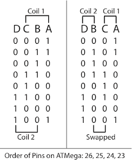 Basically the standard order is connecting the coils in alphabetic order as shown in their data sheets. This means that the coils are intertwined as shown on the left of the above picture. This wasn't how I connected them as it seemed more logical to me to attach them so the coils were attached next to each other as shown on the right. As a side note, the letters in the picture are the letters from the data sheet, the numbers are the logical output of the pins on the pins of the microcontroller, and so when in the wrong order do weird things. This meant that instead of moving, the stepper oscillated between two locations while the rest of the time, the potential difference (voltage) over the coil was zero (ie both off or both on). What I realised from testing with the help of the LEDs connected and using a slower clock speed was that I had one coil with both sides on logical 1 and the other coil on logical 0 most of the time hence why it was not working. So once I swapped the two middle columns of the logical states in the table above, it all magically started working. This was something I had not read in any of the tutorials online or in text books to be careful of so I'm quite happy that I managed to solve this for myself.
So here is my code:
(Note to self, using http://codeformatter.blogspot.com/ with settings 5 spaces per tab, no line numbering, don't remove blank lines, yes to stylesheet, auto height and no to alternative background)
Its fairly rudimentary at the moment and needs tidying up but it shows the gist. I used decimals as it was easier to test and write down than using binary numbers which I had used in my demo which wasn't working. For those interested, binary in GCC and Atmel Studio can be written down using 0b as a prefix to the binary string. The code above won't work straight from copying as I have commented out the method for changing between full steps and half steps. The other thing to note is that my chip is running at 4Mhz so the time would need to be changed if running at a slower speed.
I think that is all about getting the stepper working. Tomorrow I'll either fix it up for use with my demo program which turns certain amounts and then gives control to the buttons, or I'll have a go with serial communication to the LCD screen. I might if I have enough time, have a look at both.
Just to finish off, I was looking around Australian Robotics this afternoon and found there is a ball bearing on there which is 5mm thick with an ID of 5mm and OD of 16mm. This could potentially work for wheels on the carriage but after realising that the motor shaft is also 5mm diameter and is quite large realistically, I think a smaller shaft diameter would make more sense. The same website also has a coupler for converting the 5mm diameter shaft of the motor to 8mm which would work well for M8 threaded rod or an 8mm ball screw.
I'll should have enough stuff to post again by tomorrow night or the night after as will be at home working on it for the next few days. Should be good.
Firstly here is another video of the stepper, this time running at a decent speed, using half steps.
So I'll give the schematic next to show you the circuit layout, then I'll go into the problem I had and finally the code. The schematic does look messy, I would fix this by labelling the wires but I found out tonight that KiCAD doesn't have this functionality so it will have to do.

OK, so my problem for why the stepper wasn't working was quite trivial in the end. It turned out that I had connected the stepper in a non standard way and so the guides on programming for a stepper motor didn't work.

So here is my code:
 #include <avr/io.h>
 #include <util/delay.h>        // for _delay_ms()

 int main(void)
 {
   DDRC |= 0x0F;

      uint8_t curLED = 1;
      while (1) {
           PORTC = curLED;
           _delay_ms(7); // 18 for full steps, 7 for half steps

           /** Full Steps **
           if (curLED == 1) {
                curLED = 4;
           }
           else if (curLED == 4) {
                curLED = 2;
           }
           else if (curLED == 2) {
                curLED = 8;
           }
           else {
                curLED = 1;
           }
           **/
           /** Half Step **
           if (curLED == 1) {
                curLED = 5;
           }
           else if (curLED == 5) {
                curLED = 4;
           }
           else if (curLED == 4) {
                curLED = 6;
           }
           else if (curLED == 6) {
                curLED = 2;
           }
           else if (curLED == 2) {
                curLED = 10;
           }
           else if (curLED == 10) {
                curLED = 8;
           }
           else if (curLED == 8) {
                curLED = 9;
           }
           else {
                curLED = 1;
           }
           */
   }
   return 1;
 }
(Note to self, using http://codeformatter.blogspot.com/ with settings 5 spaces per tab, no line numbering, don't remove blank lines, yes to stylesheet, auto height and no to alternative background)
Its fairly rudimentary at the moment and needs tidying up but it shows the gist. I used decimals as it was easier to test and write down than using binary numbers which I had used in my demo which wasn't working. For those interested, binary in GCC and Atmel Studio can be written down using 0b as a prefix to the binary string. The code above won't work straight from copying as I have commented out the method for changing between full steps and half steps. The other thing to note is that my chip is running at 4Mhz so the time would need to be changed if running at a slower speed.
I think that is all about getting the stepper working. Tomorrow I'll either fix it up for use with my demo program which turns certain amounts and then gives control to the buttons, or I'll have a go with serial communication to the LCD screen. I might if I have enough time, have a look at both.
Just to finish off, I was looking around Australian Robotics this afternoon and found there is a ball bearing on there which is 5mm thick with an ID of 5mm and OD of 16mm. This could potentially work for wheels on the carriage but after realising that the motor shaft is also 5mm diameter and is quite large realistically, I think a smaller shaft diameter would make more sense. The same website also has a coupler for converting the 5mm diameter shaft of the motor to 8mm which would work well for M8 threaded rod or an 8mm ball screw.
I'll should have enough stuff to post again by tomorrow night or the night after as will be at home working on it for the next few days. Should be good.
Sunday, January 20, 2013
Major Design Change again...
I've been trying to write this post for the last five days but have been unable to find time due to work and chores round the house. So first things first, I did manage to draw a reasonably accurate illustration of the design. It helped me think of a few things I hadn't thought of yet such as the X slide motor on the I beam would need to be mounted on a plate from the front so it doesn't dragged across the angle material of the Y slide. After this point though I basically abandoned finishing the drawing. This was because I felt the canter-leaver of the X slide would be hard to secure onto the Y slide. This joint is shown with a circle, in the picture below.
 To over come this I had a small brainstorming. During this I found there was a new MendelMax (version 2). This gave me some good ideas. I wanted to still use the carriage design as I thought the current design worked quite well (more later on in this post about the carriage), so this would need to be kept in mind.
I then came up with a design fairly similar to the MendelMax version 2 above and mixed with a wharf/cargo crane.
 When I first drew this design out I thought it would be great if the whole frame could move above the work as this would save on the footprint of the printer and so save space. (This was sort of one of my aims - to have the printer so it would fit on a desk, with my desk being 600mm deep so hopefully able to fit on that with out encroaching over the edge.) I might have to abandon the frame moving idea but I'm not sure. I can use the aluminium extrusion bars mentioned in relation to the very first design, for tracks for instance but I have not evaluated this yet. The other option is to design it like the MendelMax with the work moving for one of the directions. This might seem like a back flip for my ideas, and in a way it is but all in all, the project is a learning one so its no surprise that I end up with a design similar to others. I could make sure the sliding frame would work if I didn't use aluminium and used steel for example instead but I would prefer it to be light enough to move if needed which steel would parts would not help with.
In this design the slide between the two sides could be the carriage design and the Z slide could be the same again or just use track like the bottom. I had also when first thinking of this design, to not bother with diagonals for the uprights but after looking at the MendelMax2 I thought this would be a better idea.
I then started designing the carriage that I think is a good idea in Inventor. I haven't finished it yet but here are some pictures showing my ideas. I also haven't finalised on dimensions or locations so some parts are out of place. The four wheels that roll along the centre part of the I beam will have holes cut into the rectangular hollow so they have enough room to spin while also allowing the material to protrude in enough that the wheels in the upright position have somewhere to mount on both sides.


 The diagrams above also have a very key part missing, that is the mechanism that joins the wheels to the aluminium. I'll attach them as shown in the following image.


I then came up with a design fairly similar to the MendelMax version 2 above and mixed with a wharf/cargo crane.

In this design the slide between the two sides could be the carriage design and the Z slide could be the same again or just use track like the bottom. I had also when first thinking of this design, to not bother with diagonals for the uprights but after looking at the MendelMax2 I thought this would be a better idea.
I then started designing the carriage that I think is a good idea in Inventor. I haven't finished it yet but here are some pictures showing my ideas. I also haven't finalised on dimensions or locations so some parts are out of place. The four wheels that roll along the centre part of the I beam will have holes cut into the rectangular hollow so they have enough room to spin while also allowing the material to protrude in enough that the wheels in the upright position have somewhere to mount on both sides.


This is a change from what I had previously designed. This is due to the previous design only being attached in one place and at 90 degrees so if there managed to be forces in the wrong location is was much more prone to damage.
Recently while trying to think of other uses for the printer I've worked out I could potentially use the printer for CNC drilling which would be great for doing circuit boards. Out of this same idea I thought the extruders could also be used for solder as it runs about the same temperature as PLA.
I've now gone back to having a look at the electronics. I've had a quick look at the stepper motor driver. I've attached some LEDs to each of the leads. This means that if neither LED is on for a coil then its off, same when both are on and if only one of the two for each coil is on then it should be positive or negative 12V. At the moment though it seems to have both on for one coil and both off for the second coil and hence why the motor does not spin. I'll write a test program that turns on each pin separately on the ATMega and see of I can get it to go to each state. If this doesn't work I'll have a look at the wiring and maybe redo it. If this still doesn't work, I managed to solder the SMD stepper controller on Friday with just a normal soldering iron and so can try that out.
With regards to the display, I'm going to try the serial connection which I said before. This looks to be much easier than I2C but does mean I can't use serial for anything else. This isn't such a concern as I can use SPI for connecting the controllers together.
This next week I have more time to work on the project as I'm not at work for two full days so should be able to spend more time on it as it seems like ages since I did anything even though its only been 4 or 5 days.
Saturday, January 12, 2013
Frame Ideas
Well, even though I have been at work the last couple of days, I have still managed to to some design work. Before work on Wednesday I did another drawing of the extruder from another angle to help show some of the features a tad better.
 This shows the drive gear being directly driven by the motor. This has since changed a number of times. After the direct drive idea, I though a worm drive would be a better idea. This worked until I started designing how to attach the extruder to the frame. The worm drive gear was then thought could be used in combination with helical or bevel gears but I realised these would be too hard to machine at home on our mill and lathe as we don't have a geared dividing head. At this point I better add why I want to use a worm drive. This because I firstly want there to be plenty or torque for pushing the filament and second to that but not as important in this case, accuracy of how much is being pushed down the nozzle. I have finally gone with simply using two gears with a high enough gear and torque ratio. I haven't yet drawn an illustration of this situation. I still reckon I will use a worm drive on the Z slide though as the torque would be very useful for pushing the slides up when gravity is trying to push everything down.
I next sat down, and with a copy of the previous design (as shown in the last post), and drew over it.
 With this, I tried to decide on materials for each section of the frame. In the last post I had been thinking of using angular or channel extrusions for the X slide. I realised that this would not work due to the unsymmetrical mass and thus twist of the materials would occur and cause inaccuracies and possibly breakages after a time. That is what all the pictures of beam types are in the top corner. I've written around them why I haven't chosen them. The Y slide I'm going to go with angle regardless as its otherwise too hard to attach the X slide. I'll instead just make this sturdy enough that twist won't be great enough to worry about. This drawing also shows that the bar on top, needs only be a tie bar for strength purposes. It may still not just be used as a tie bar due to aesthetics. The main frame, as in the materials for the Z slide and base will all be square tubing. With the base, I came across a page on the reprap site about calibration and it recommended if there was a heated bed, that it be 110˚C for PLA. With this in mind, I'm going to install insulators between the bed and the frame itself. I don't think I've said anywhere else so may as well state the sort of obvious. The frame at the bottom will also have a bar attaching the two legs of the frame together. This is obviously needed for strength and to tie the frame together.
So the type of material I decided on for the X slide was an I beam. This was due to twist and sturdiness.
 I think I will join the X and Y slides similar to the above picture, but I haven't done any analysis on this joint so has potential to change. The green part (the colours are just to show different parts) bends down the back of the red one so it can slip forwards too much. I may be able to put a grove in the back of the red part so the green one latches in and is unable to fall out.
The next day at work, I decided I would have a go trying to think of how to fit an extruder onto this I beam. I came up with a nice carriage idea and a new extruder that had an angled/L shaped nozzle.
 I soon realised that an angled nozzle was a bad idea as it had the forces in the wrong direction to get the filament down the other end and would be very hard to clean which would be needed if a change of filament colour was wanted. So I scraped this idea and went back to the original extruder. I'll balance out the weight by moving the motor to the other side of the carriage from the nozzle and the rest of the drive. The carriage shown also has the slide drive above the carriage. I think I will move this to one of the sides so that it takes away height, plus I can have this motor on the top and the motor for the Y slide underneath. This would mean that I can use that space used by the motor on the Y slide more effectively. To make more sense of the image above I also made another image showing one side of the carriage wheel arrangement.
 This arrangement works by having wheels in the Z direction pushing against each other and so making the carriage centred in the Z direction while taking out bumps. The wheel in the Y direction is used to centre the carriage in the Y direction and is used by pushing against the wheel on the other side of the I beam. The arrangement of three wheels for the Z direction on each side is so the carriage doesn't rotate.
Hopefully in the next few days, I'll do a proper mechanical sketch which will combine all of these ideas into one image. I was going to do it today but I have had to do some other wood work so to start tidying up dad's shed for his use.
Other ideas I have had for the frame is too have gyroscopes on the head/carriage and one on the bed so corrections can be made automatically for any twist. This idea was always the case, I just needed to write it down. I will put micro switches on the slides so the electronics can work out its maximum travel distances. I'm also going to have to weigh the stepper motor sometime so once I've done the basic design, I can check material strengths and balance out the weight on parts such as the extruder carriage.
One last thing before I finish this post. A while ago I posted an invention that you could use to melt down old plastic bottles and convert to filament. During the week I was thinking about this and I think I will make one of these almost as soon as I've made the printer. This is because its far cheaper to melt down plastic you already have and recycle rather than always buy it. I also had a quick look on the net and found you can buy plastic pigment for colouring so this could be added to get colours. With this machine, if I was to make one, I would try and make it mostly automatic and so it would melt down the plastic given, add the pigment and mix then extruder out through a hot nozzle into a cold nozzle and then automatically roll it up. The cold nozzle is used so the plastic doesn't melt together when rolled up.
Well that is all for this post, hopefully tomorrow I'll have a new image of all the above components together but it may be Tuesday or Wednesday before I get it done.

I next sat down, and with a copy of the previous design (as shown in the last post), and drew over it.

So the type of material I decided on for the X slide was an I beam. This was due to twist and sturdiness.

The next day at work, I decided I would have a go trying to think of how to fit an extruder onto this I beam. I came up with a nice carriage idea and a new extruder that had an angled/L shaped nozzle.


Hopefully in the next few days, I'll do a proper mechanical sketch which will combine all of these ideas into one image. I was going to do it today but I have had to do some other wood work so to start tidying up dad's shed for his use.
Other ideas I have had for the frame is too have gyroscopes on the head/carriage and one on the bed so corrections can be made automatically for any twist. This idea was always the case, I just needed to write it down. I will put micro switches on the slides so the electronics can work out its maximum travel distances. I'm also going to have to weigh the stepper motor sometime so once I've done the basic design, I can check material strengths and balance out the weight on parts such as the extruder carriage.
One last thing before I finish this post. A while ago I posted an invention that you could use to melt down old plastic bottles and convert to filament. During the week I was thinking about this and I think I will make one of these almost as soon as I've made the printer. This is because its far cheaper to melt down plastic you already have and recycle rather than always buy it. I also had a quick look on the net and found you can buy plastic pigment for colouring so this could be added to get colours. With this machine, if I was to make one, I would try and make it mostly automatic and so it would melt down the plastic given, add the pigment and mix then extruder out through a hot nozzle into a cold nozzle and then automatically roll it up. The cold nozzle is used so the plastic doesn't melt together when rolled up.
Well that is all for this post, hopefully tomorrow I'll have a new image of all the above components together but it may be Tuesday or Wednesday before I get it done.
Tuesday, January 8, 2013
Extruder Nozzle CAD and materials for Frame
Well today I actually got some CAD done! I modelled the nozzle for the extruder and the insulator, which I posted about yesterday. The designs I had yesterday weren't complete as they had no dimensions and were really just pretty pictures (not even very pretty some of them). I also changed a few things about them along the way. Just of note, I'm going to post my hand drawn designs as well as the CAD ones in this post which I won't do normally as there isn't much point in uploading both except for looking at my effort at drawing and seeing how it fairs to what I actually design. So here is the page of designs.
As you can see from this, I have designed and given numerical values to dimensions except where I'm unsure or I'm going with a standard. Next thing to notice is that I have started to assign part numbers. I wasn't going to do this but I realised when I was drawing these that if I do a parts list on Inventor that it always shows a parts list plus when I save the files it makes it neater to have standardised file names rather than the hodgepodge that I normally do have. I thought for ideas I better have a read about part numbering and found that some company called Arena Solutions had some nice pages about part numbering here and here. I then went with a 11 character (excluding dashes) with an extra 2 digits if needed. There were as follows:
3 characters for the significant (major) location or use of the part
3 characters for the minor location or use of part with the significant one (major)
4 numbers for the revision
and the optional 2 numbers that are used for types of a part such as with the nozzle, there will be at least two versions of the same nozzle, one with a smaller extrusion hole (ie the bit where the plastic comes out) and one with a larger one hole.
While I was looking round for dimensions for the nozzle I also came across a page on the RepRap site that had some variations of the standard nozzles. One of these used PEEK plastic for something and was attached to the nozzle so I checked it out and its melting temperature is 343 degrees according to wikipedia so is another contender along with the ones mentioned in the last post which were polyurethane (no melting point), Kevlar (500˚), Twaron (500˚), Nomex (390˚) and PTFE (330˚).
Another page I found when wondering about the size of filament to use was a forum page talking about the best sizes. This explained that larger nozzles can actually be better for larger prints as sometimes these don't need too much detail and so a larger nozzle will be faster. The page also recommended starting with a 1.75mm filament that although slightly more expensive, would melt quicker and so easier to use and not as much pressure would be required.
The red note (which was partially cut off by the scanner) in the bottom of the page is about the potential of plastic to melt into the crevasse between the end of the nozzle bolt and the nozzle tip. I had thought this would be an issue and have to create a revision that had all the tubes and diameter changes all part of the bolt and just use the tip as metal mass and for using as the storage for the heating element and sensor (with some heat sink fluid between the two parts). After some thought I decided this wouldn't matter as it would fill up and stay there. It could also be fixed using a high temperature sealant such as silicone of which there seemed to be plenty selling online. We shall see how it turns out once we make it. The only reason to be worried is for cleaning and changing the colour of the filament used.
So after all of that, here is my CAD version of the nozzle.
 I had to upload it as a PNG rather than PDF so its lost some of the detail and the page size which is supposed to be A3. Here is a link to the PDF version on my Google drive. The only real difference between this and the design I had yesterday are that the locations for the heating element and temperature sensor are now holes that go straight through the nozzle rather than being at a weird angle. There is also one dimension that I've added a numerical value to but will have to be adjusted. This is the length of the thread on the bolt as it depends on the thickness of the casing/wall that holds the nozzle.
So that covers what I've done with the nozzle today. As I said I won't write up everything from the preliminary designs in the future I don't think but we'll see how I feel on the day.
The other thing I did today very briefly was to think about the materials for the frame. I'm still working off the design I posted a while ago.
 Apart from I'm going with what I said yesterday which was to use U shaped channel for the X slide. I think I will also use it for the Y slide now too. This is because it is much stronger laterally that just a bar which is what I had drawn in my original design and even today was thinking about. I think the bulk of the main frame will be out of square hollow tube with the sides being either 45 or 50mm. I was also thinking of using a special type of aluminium extrusion for the Y slide and top. It looks similar to the next image which I had seen when I did a tour round a high speed boat builder site. I think though it was specially made and most likely wouldn't be made small enough.
 This was the stage were I thought flat bars would be a good idea but as I said above I've reconsidered and think channel will be a better idea.
Well that is all for this post. I'm working the next few days so won't be able to write any more posts but I'm sure I'll be thinking of ideas as I'm working.
 |
3 characters for the significant (major) location or use of the part
3 characters for the minor location or use of part with the significant one (major)
4 numbers for the revision
and the optional 2 numbers that are used for types of a part such as with the nozzle, there will be at least two versions of the same nozzle, one with a smaller extrusion hole (ie the bit where the plastic comes out) and one with a larger one hole.
While I was looking round for dimensions for the nozzle I also came across a page on the RepRap site that had some variations of the standard nozzles. One of these used PEEK plastic for something and was attached to the nozzle so I checked it out and its melting temperature is 343 degrees according to wikipedia so is another contender along with the ones mentioned in the last post which were polyurethane (no melting point), Kevlar (500˚), Twaron (500˚), Nomex (390˚) and PTFE (330˚).
Another page I found when wondering about the size of filament to use was a forum page talking about the best sizes. This explained that larger nozzles can actually be better for larger prints as sometimes these don't need too much detail and so a larger nozzle will be faster. The page also recommended starting with a 1.75mm filament that although slightly more expensive, would melt quicker and so easier to use and not as much pressure would be required.
The red note (which was partially cut off by the scanner) in the bottom of the page is about the potential of plastic to melt into the crevasse between the end of the nozzle bolt and the nozzle tip. I had thought this would be an issue and have to create a revision that had all the tubes and diameter changes all part of the bolt and just use the tip as metal mass and for using as the storage for the heating element and sensor (with some heat sink fluid between the two parts). After some thought I decided this wouldn't matter as it would fill up and stay there. It could also be fixed using a high temperature sealant such as silicone of which there seemed to be plenty selling online. We shall see how it turns out once we make it. The only reason to be worried is for cleaning and changing the colour of the filament used.
So after all of that, here is my CAD version of the nozzle.

So that covers what I've done with the nozzle today. As I said I won't write up everything from the preliminary designs in the future I don't think but we'll see how I feel on the day.
The other thing I did today very briefly was to think about the materials for the frame. I'm still working off the design I posted a while ago.


Well that is all for this post. I'm working the next few days so won't be able to write any more posts but I'm sure I'll be thinking of ideas as I'm working.
Monday, January 7, 2013
Extruders and more!
Its been what seems an age since my last post. This is because, after exams finished, I just sort of switched off from everything and relaxed, specially with extended family coming to visit and Christmas and New Years. For New Years I was away on a trip to Melbourne, and one night decided I would plot some ideas down and so have now got right back into the project.
So since my last post, and before my planning in Melbourne, not a lot has happened. I still haven't managed to get my display to work using I2C, so I may switch to serial unfortunately. I did however manage to get the stepper motor to move... slightly, as in it sort of flicks between two spots. Below I have added my notes of the test program and the driver code. I had to stop progress as the extended family needed to use my room (I was kicked out of my own room!) as well as it being summer here and having great conditions for the beach and other activities to relax. I'll shall get to these soon as I thought of a very loose plan of phases I need to do.
I'll now go through the things I decided on and thought about while in Melbourne. First up my phases, which I split up into electronics based and mechanical/structural based. This is so I don't get board or annoyed when something is taking too long or is turning out as planned and thus can move to the other stream. I also have some notes on these.
So the electrical phases are:
1) Create and test motor controller (ie what I have been doing with the steppers recently)
2) Test SPI between two ATMegas (get two microcontrollers communicating)
3) Get the display working (I want to do this sooner rather than later as would be great for debugging)
4) SD Card (There are plenty of tutorials on this and would be the easiest way of getting the data from the computer to the chips until I have ethernet working)
5) G Code and related (the syntax used to tell the printer what to do)
6) Combine the above including porting some of the code for use on smaller chips
7) Ethernet (So can print without having to be next to the printer)
The mechanical phases are:
1) Design frame on AutoDesk Inventor
2) Design single based extruder (partly done as I wrote this list without a computer at hand so my mind wandered and started designing an extruder regardless which I obviously wrote down)
3) Review (I say this as I'm sure I will design something and then realise that it won't work or something could be done better. Ie look at it with a different frame of mind.)
4) Add/make sure there are mounts incorporated in the design such as screw holes, types of screws, tolerances etc.
5) Do the cable layouts, this will make the end product neater, more aesthetically appealing but more importantly make sure the cable will actually fit where needed and where sockets and plugs need to go.
6) Build
7) Test
8) Multiple extruder
The notes I have are as follows:
• KiCAD layouts can be exported and thus can be imported into Inventor for use in designing mounts etc
• The SD Card should have higher priority than ethernet as mentioned above
• By using G-Code and related it is easier to use pre existing utilities until we are able to and decide to create a better one - we'll need to at least create a utility that can send via ethernet.
• On the same lines as the above, if the G-Code for 3D printers is different from that of normal CNC machines such as mills, then both will hopefully be implemented with the 3D printer version taking priority as there are more utilities are available.
• Drawings (well the inventor models) should include physics ie, hopefully can simulate motor turning and have slides move.
Now we finally get to the extruders which I designed the last few days. I can't take all credit for the design of this extruder as, like I have previously mentioned, I have been very inspired by the RepRap designs. I also had some ideas from the Ben Heck Show on YouTube as he has made a bunch of 3D printers, one of which (the one I have actually watched as it was uploaded just before Christmas) is a "Double Decker 3D printer". This can print two of the same objects at once. This helped me as it showed how the design from RepRap actually was constructed rather than just a still picture from one or two angles. One of the things I noticed was that Ben was using timber for the frame. I realised this also meant it would also act as an insulator for the extruder to stop excess heat transferring to the rest of the model. Other extruders I have seen pictures of have not had any sort of insulator (well not that I had noticed) and so I think this would be a good improvement. It also allows the casing or structural components to be made of metal too while not having to worry about heat issues. I will if I use metal casing have to make braces and diagonals but I think that is better than having bulky extruders which would mean it is harder to incorporate multiple extruders. I'm also still thinking of trying to use U shaped channel for the slide that the extruder is on. This would mean that a small slot down the middle could be used as a guide and as a hole for the hot tip to be mounted through. The two edges could be easily used for guides too.

 This image, is a much clearer and better defined version of the illustration in the top left of the previous image. This has everything labelled and so not much explanation is needed. The spring arm is used so the filament is always wedged against the drive/push gear and thus has grip. The note down the bottom about a worm gear is so the motor has more torque against the filament. The other note at the bottom is simply there to remind me that the drive gears should have teeth so to better grip the filament, hopefully with the middle of the teeth curved a little so to have more surface area on the filament rather than just the centre which would be the case if the teeth were flat on top.

This last image is about the slide, simply showing potential of a U shaped slide.
The next thing I designed, was when I got back. I was looking over the 2012 in review post on the RichRap Blog and re-found the post on his paste extruder. I had originally decided this wasn't for me as it used a syringe which wouldn't hold enough paste to be useful but while having a few mates round for drinks, one of them came up with the idea of just using a syringe and then pumping or sucking more paste into the syringe. So once reminded of this post I had a look at how his syringe extruder worked and quickly realised the design he had used would not work for me as it would only work in one direction and thus would not be able to suck. (I think sucking will be better than pumping as it requires less parts and thus less expensive, plus if it doesn't work is much easier to convert to pump than it is to ignore sucking the first time round and then be stuck if pumping doesn't work.) So while trying to think of how to do this, I checked wikipedia for how to spell actuator (it was almost midnight and I was half asleep so I was trying to spell actuator like auxiliary with the start being aux and so couldn't get spell check to fix it.) One the wikipedia page, I saw screws could be used as a basic actuator (not that I didn't know this, it just wasn't at the forefront of my head at the time) and so realised this would be the best way to implement the actuator so it can move the syringe both up and down.
 The reason for two drive gears is to get extra torque as sucking would require quite a lot. The other two notable things I thought about this design is that due to the pipe bringing more paste in, that this pipe would need to be turned on and off so not to have the paste pushed back down it, and so a gate controlled by a solenoid would be needed. When sucking material back, there could also potentially be excess air in the pipe or something so a pressure sensor could be used to detect the pressure and therefore work out if it needs to let some air out. The other way of doing this could be to make the gate over the needle out of material that would let air out (though not in).
That is all of the ideas I have come up with over the last few days, but there were some others that I had written down to type up on the blog. Firstly I found a tutorial for SMD soldering using standard solder, a standard soldering iron and de-soldering wick. I thought it seemed like a good idea but the comments when I just checked now seem to indicate otherwise. It also sort of states the obvious but still something I had not thought about which was to use tweezers when handling SMD parts.
A few posts ago I had thought a camera would be nice to incorporate. I soon realised the camera modules were actually quite hard to find for some reason and seem to have to be ordered direct from the manufacturers. I have since found one from Little Bird Electronics.
Another thing I had thought of was to engrave each slide with the name its known by software, as this would make it far easier to debug and understand what settings were being changed etc. Talking of engraving, I've decided I would love a laser cutter! Within a week I had two completely non related people say I should get one with me having investigated them too that same week before anyone had said anything. They seem great, and would be great for cutting shapes out of wood, flat plastic and metals. This in conjunction with out press that can bend metal into shape would be great for making brackets and things like cases such as for the extruder above. One can only dream though.
And so to finish off this post, I'll say one last thing which I had realised when I was testing the stepper motors back in November. For something that makes mechanical/structural items, it has large amounts of electronics involved!
So since my last post, and before my planning in Melbourne, not a lot has happened. I still haven't managed to get my display to work using I2C, so I may switch to serial unfortunately. I did however manage to get the stepper motor to move... slightly, as in it sort of flicks between two spots. Below I have added my notes of the test program and the driver code. I had to stop progress as the extended family needed to use my room (I was kicked out of my own room!) as well as it being summer here and having great conditions for the beach and other activities to relax. I'll shall get to these soon as I thought of a very loose plan of phases I need to do.
 |
| The flow of the stepper test program (left), and the combination of the digital logic for the L293 chip (right) |
I'll now go through the things I decided on and thought about while in Melbourne. First up my phases, which I split up into electronics based and mechanical/structural based. This is so I don't get board or annoyed when something is taking too long or is turning out as planned and thus can move to the other stream. I also have some notes on these.
So the electrical phases are:
1) Create and test motor controller (ie what I have been doing with the steppers recently)
2) Test SPI between two ATMegas (get two microcontrollers communicating)
3) Get the display working (I want to do this sooner rather than later as would be great for debugging)
4) SD Card (There are plenty of tutorials on this and would be the easiest way of getting the data from the computer to the chips until I have ethernet working)
5) G Code and related (the syntax used to tell the printer what to do)
6) Combine the above including porting some of the code for use on smaller chips
7) Ethernet (So can print without having to be next to the printer)
The mechanical phases are:
1) Design frame on AutoDesk Inventor
2) Design single based extruder (partly done as I wrote this list without a computer at hand so my mind wandered and started designing an extruder regardless which I obviously wrote down)
3) Review (I say this as I'm sure I will design something and then realise that it won't work or something could be done better. Ie look at it with a different frame of mind.)
4) Add/make sure there are mounts incorporated in the design such as screw holes, types of screws, tolerances etc.
5) Do the cable layouts, this will make the end product neater, more aesthetically appealing but more importantly make sure the cable will actually fit where needed and where sockets and plugs need to go.
6) Build
7) Test
8) Multiple extruder
The notes I have are as follows:
• KiCAD layouts can be exported and thus can be imported into Inventor for use in designing mounts etc
• The SD Card should have higher priority than ethernet as mentioned above
• By using G-Code and related it is easier to use pre existing utilities until we are able to and decide to create a better one - we'll need to at least create a utility that can send via ethernet.
• On the same lines as the above, if the G-Code for 3D printers is different from that of normal CNC machines such as mills, then both will hopefully be implemented with the 3D printer version taking priority as there are more utilities are available.
• Drawings (well the inventor models) should include physics ie, hopefully can simulate motor turning and have slides move.
Now we finally get to the extruders which I designed the last few days. I can't take all credit for the design of this extruder as, like I have previously mentioned, I have been very inspired by the RepRap designs. I also had some ideas from the Ben Heck Show on YouTube as he has made a bunch of 3D printers, one of which (the one I have actually watched as it was uploaded just before Christmas) is a "Double Decker 3D printer". This can print two of the same objects at once. This helped me as it showed how the design from RepRap actually was constructed rather than just a still picture from one or two angles. One of the things I noticed was that Ben was using timber for the frame. I realised this also meant it would also act as an insulator for the extruder to stop excess heat transferring to the rest of the model. Other extruders I have seen pictures of have not had any sort of insulator (well not that I had noticed) and so I think this would be a good improvement. It also allows the casing or structural components to be made of metal too while not having to worry about heat issues. I will if I use metal casing have to make braces and diagonals but I think that is better than having bulky extruders which would mean it is harder to incorporate multiple extruders. I'm also still thinking of trying to use U shaped channel for the slide that the extruder is on. This would mean that a small slot down the middle could be used as a guide and as a hole for the hot tip to be mounted through. The two edges could be easily used for guides too.

This was my first sketch and ideas page, hence why its quite messy. Most of the drawings, except for the one in the top left are of ways to try and make a mechanism that would allow multiple extruders to be used with a plate that would allow only one of these extruders to be operational, ie only allow one extruder to have a clear hole/access down to the work below. This is also the reason for the question in the top left, as if the plastic won't drip, we won't need such a mechanism and can just stop pushing the plastic or pull it back a bit to create a vacuum. These mechanisms would be operational with the use of solenoids or motors, both being expensive and hence why its better to try and avoid such mechanisms.


This drawing is purely about the tip/hot end on the extruder. The insulator bits show a large extrusion for the internal hole, but this need not be so big, just big enough so it sits in the case material. The question which I'm not sure if it will be readable on the uploaded image is asking what the size of the tip itself should be as a larger tip would have a larger heat capacity and thus not need as much energy to keep at the same temperature but its large, so would a smaller one but with less heat capacity be better. The other important thing on this page is the material for this insulator. I short listed a few which all have melting points supposedly higher but I'm not sure about expense, availability or the operating temperatures.
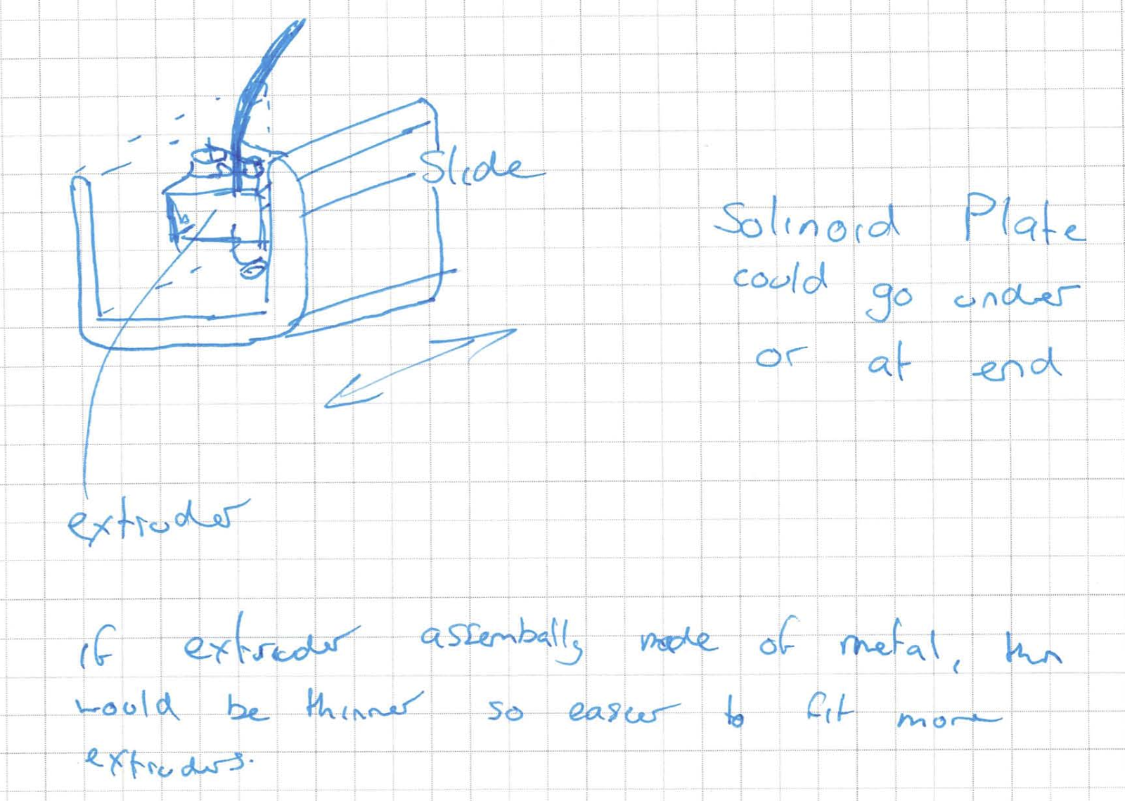
This last image is about the slide, simply showing potential of a U shaped slide.
The next thing I designed, was when I got back. I was looking over the 2012 in review post on the RichRap Blog and re-found the post on his paste extruder. I had originally decided this wasn't for me as it used a syringe which wouldn't hold enough paste to be useful but while having a few mates round for drinks, one of them came up with the idea of just using a syringe and then pumping or sucking more paste into the syringe. So once reminded of this post I had a look at how his syringe extruder worked and quickly realised the design he had used would not work for me as it would only work in one direction and thus would not be able to suck. (I think sucking will be better than pumping as it requires less parts and thus less expensive, plus if it doesn't work is much easier to convert to pump than it is to ignore sucking the first time round and then be stuck if pumping doesn't work.) So while trying to think of how to do this, I checked wikipedia for how to spell actuator (it was almost midnight and I was half asleep so I was trying to spell actuator like auxiliary with the start being aux and so couldn't get spell check to fix it.) One the wikipedia page, I saw screws could be used as a basic actuator (not that I didn't know this, it just wasn't at the forefront of my head at the time) and so realised this would be the best way to implement the actuator so it can move the syringe both up and down.

That is all of the ideas I have come up with over the last few days, but there were some others that I had written down to type up on the blog. Firstly I found a tutorial for SMD soldering using standard solder, a standard soldering iron and de-soldering wick. I thought it seemed like a good idea but the comments when I just checked now seem to indicate otherwise. It also sort of states the obvious but still something I had not thought about which was to use tweezers when handling SMD parts.
A few posts ago I had thought a camera would be nice to incorporate. I soon realised the camera modules were actually quite hard to find for some reason and seem to have to be ordered direct from the manufacturers. I have since found one from Little Bird Electronics.
Another thing I had thought of was to engrave each slide with the name its known by software, as this would make it far easier to debug and understand what settings were being changed etc. Talking of engraving, I've decided I would love a laser cutter! Within a week I had two completely non related people say I should get one with me having investigated them too that same week before anyone had said anything. They seem great, and would be great for cutting shapes out of wood, flat plastic and metals. This in conjunction with out press that can bend metal into shape would be great for making brackets and things like cases such as for the extruder above. One can only dream though.
And so to finish off this post, I'll say one last thing which I had realised when I was testing the stepper motors back in November. For something that makes mechanical/structural items, it has large amounts of electronics involved!
Thursday, November 1, 2012
More Electronics
I still have exams, hence I'm still avoiding long periods of time on the structural side of things.
Since the last post I've had a look into ARM programming as I didn't understand how they were programmed (physically as in the connection type and protocol). I found out that in general they are programmed with JTAG using a 10pin IDC connector but can use a 20 pin connector for debugging. This was different from what I was expecting as I thought there would be far fewer pins like the smaller chips have that tend to have 4-6 pins (though I have only just got into the world of microcontrollers). While doing research I found a nice website that explained how to do the programming and downloading/flashing with open source tools. Basically uses standard GCC tools along with a tool called OpenOCD which is the flasher and debugger.
In terms of the actual chips, I found a number of manufacturers. I only really want microcontroller style chips (ie without graphics and related) so I excluded chips from the likes of Samsung that are more geared towards smart phones and tablets. So the manufacturers I'm considering are Atmel, STM (STMicroelectronics) and Qualcomm. I'm leaning towards STM as they seem to have good range and value. I've just checked the OpenOCD and found a page that says which programmers it supports, here. I think I will go for the ST-LINK/V2 as it is cheap ($28.40) though does only work with STM chips. The other option I think is the Segger J-Link which is more expensive at $67.62 but should support multiple manufacturers.
For communication between the controllers, I had previously said that I2C would be what I would use and on the slave controllers could use binary switches to choose an address. Since then I decided I would take off the switches to make the boards smaller, combining with using an ATTiny rather than an ATMega for an even smaller footprint. In the last week I have also decided I will move away from I2C due to speed and complexity in coding. Instead I will use SPI, which although needs slave select lines, the use of a multiplexer can be used to ease the number of pins needed on the master controller. SPI brings the advantages that its faster and is less prone to errors. Some good information about the two can be found on stackexchange.
Next I have ordered and received the stepper motors. This is good as I can now get the weight for force calculations and I can start designing the circuit for controlling them. The only other large weight for slides are the ball screws which I will purchase after I've design the surrounding structure and the stepper driver circuits. I might also need to include gearing of some sort on the z slides as the gravitational force may try and turn the ball screws and the holding torque might not hold this. I'll have to wait till I design it to see what happens.
Talking about the stepper motors, I've decided to go with a dedicated stepper motor controller chip. This is because, the cost of these chips are far cheaper than all the parts to make one the equivalent controller are combined. There are two chips I've looked into and these are the L293 and the A3982. The L293 has a DIP packet so is easier to prototype with but is more a general motor controller and so it needs four or five pins for control. The A3982 chip is SMD SOIC thus is hard to prototype with but is specifically designed to control bipolar stepper motors. I'm going to get one of each chip and have a practise with both to see what is the best fit but I think the A3982 will be the go. To overcome the SMD SOIC problem, I'm going to buy some breakout boards for prototyping. I'm going to buy my boards from Little Bird Electronics as are based in Australia so hence shipped here and were cheap. I had previously found places in Singapore and the UK but they didn't ship here and were too expensive retrospectively. I can then, at a later stage, go to a specialised PCB that the chip can mount directly onto, ie the slave controller board.
For soldering the SMD to the breakout boards and PCBs, I'm going to use the hotplate method that is described here and in the links contained in that link. This is easy and cheap plus I can reuse the hotplate for other workshop activities and experiments. I'm also thinking of investing in a tank etcher as from my research they have better accuracy thus meaning thinner tracks can be made. We have a tray for doing PCBs at home though so this is a purchase that I think will have to wait till I have surplus money again.
Going back to the slides once again, well the z slide in particular, I'm thinking I'll simply connect the two motors together onto the one driver. This is because otherwise the slide could potentially become uneven and so not be accurate. The other options are to drive from just one side and hope there is not enough of a moment to cause inaccuracy, (probably in conjunction with tight tolerances on the slides/guides themselves). The third option is to drive the slide from the middle. I decided that these other methods were not as practical or accurate due to forces and my original idea of having each on a separate controller was also less accurate due to each controller being communicated with separately and thus causing a timing delay.
To finish off with I have some smaller ideas for neatness, usability and ease of use. Firstly I think the wiring for the controllers back to the master controller should be put inside plastic tubing. This is good for mounting and looks neat. The next idea is to put and optical sensor above each extruder to check if there is plastic/filament available. An idea for heating is to put an apex or some other type of shaping at the top of the casing to funnel the heat to a specific spot to then fan off as this would help with temperature evenness rather some parts being affected more than others. Finally two feature that I can implement after I've got the printer mostly working. The first one of these is to set up the GUI so a pre-made object can be split to have different colours. I think I would somehow manage this by using an overlay technique which then gets analysed to get which parts want different colours and can then modify the code sent to the printer. The last and final idea I had is purely for awesomeness. This is simply a camera attached with streaming ability via the network. This means you could watch work being created without having to be next too it, or record something being made or check progress when not on location.
Since the last post I've had a look into ARM programming as I didn't understand how they were programmed (physically as in the connection type and protocol). I found out that in general they are programmed with JTAG using a 10pin IDC connector but can use a 20 pin connector for debugging. This was different from what I was expecting as I thought there would be far fewer pins like the smaller chips have that tend to have 4-6 pins (though I have only just got into the world of microcontrollers). While doing research I found a nice website that explained how to do the programming and downloading/flashing with open source tools. Basically uses standard GCC tools along with a tool called OpenOCD which is the flasher and debugger.
In terms of the actual chips, I found a number of manufacturers. I only really want microcontroller style chips (ie without graphics and related) so I excluded chips from the likes of Samsung that are more geared towards smart phones and tablets. So the manufacturers I'm considering are Atmel, STM (STMicroelectronics) and Qualcomm. I'm leaning towards STM as they seem to have good range and value. I've just checked the OpenOCD and found a page that says which programmers it supports, here. I think I will go for the ST-LINK/V2 as it is cheap ($28.40) though does only work with STM chips. The other option I think is the Segger J-Link which is more expensive at $67.62 but should support multiple manufacturers.
For communication between the controllers, I had previously said that I2C would be what I would use and on the slave controllers could use binary switches to choose an address. Since then I decided I would take off the switches to make the boards smaller, combining with using an ATTiny rather than an ATMega for an even smaller footprint. In the last week I have also decided I will move away from I2C due to speed and complexity in coding. Instead I will use SPI, which although needs slave select lines, the use of a multiplexer can be used to ease the number of pins needed on the master controller. SPI brings the advantages that its faster and is less prone to errors. Some good information about the two can be found on stackexchange.
Next I have ordered and received the stepper motors. This is good as I can now get the weight for force calculations and I can start designing the circuit for controlling them. The only other large weight for slides are the ball screws which I will purchase after I've design the surrounding structure and the stepper driver circuits. I might also need to include gearing of some sort on the z slides as the gravitational force may try and turn the ball screws and the holding torque might not hold this. I'll have to wait till I design it to see what happens.
 |
| The stepper motors |
Talking about the stepper motors, I've decided to go with a dedicated stepper motor controller chip. This is because, the cost of these chips are far cheaper than all the parts to make one the equivalent controller are combined. There are two chips I've looked into and these are the L293 and the A3982. The L293 has a DIP packet so is easier to prototype with but is more a general motor controller and so it needs four or five pins for control. The A3982 chip is SMD SOIC thus is hard to prototype with but is specifically designed to control bipolar stepper motors. I'm going to get one of each chip and have a practise with both to see what is the best fit but I think the A3982 will be the go. To overcome the SMD SOIC problem, I'm going to buy some breakout boards for prototyping. I'm going to buy my boards from Little Bird Electronics as are based in Australia so hence shipped here and were cheap. I had previously found places in Singapore and the UK but they didn't ship here and were too expensive retrospectively. I can then, at a later stage, go to a specialised PCB that the chip can mount directly onto, ie the slave controller board.
For soldering the SMD to the breakout boards and PCBs, I'm going to use the hotplate method that is described here and in the links contained in that link. This is easy and cheap plus I can reuse the hotplate for other workshop activities and experiments. I'm also thinking of investing in a tank etcher as from my research they have better accuracy thus meaning thinner tracks can be made. We have a tray for doing PCBs at home though so this is a purchase that I think will have to wait till I have surplus money again.
Going back to the slides once again, well the z slide in particular, I'm thinking I'll simply connect the two motors together onto the one driver. This is because otherwise the slide could potentially become uneven and so not be accurate. The other options are to drive from just one side and hope there is not enough of a moment to cause inaccuracy, (probably in conjunction with tight tolerances on the slides/guides themselves). The third option is to drive the slide from the middle. I decided that these other methods were not as practical or accurate due to forces and my original idea of having each on a separate controller was also less accurate due to each controller being communicated with separately and thus causing a timing delay.
To finish off with I have some smaller ideas for neatness, usability and ease of use. Firstly I think the wiring for the controllers back to the master controller should be put inside plastic tubing. This is good for mounting and looks neat. The next idea is to put and optical sensor above each extruder to check if there is plastic/filament available. An idea for heating is to put an apex or some other type of shaping at the top of the casing to funnel the heat to a specific spot to then fan off as this would help with temperature evenness rather some parts being affected more than others. Finally two feature that I can implement after I've got the printer mostly working. The first one of these is to set up the GUI so a pre-made object can be split to have different colours. I think I would somehow manage this by using an overlay technique which then gets analysed to get which parts want different colours and can then modify the code sent to the printer. The last and final idea I had is purely for awesomeness. This is simply a camera attached with streaming ability via the network. This means you could watch work being created without having to be next too it, or record something being made or check progress when not on location.
Saturday, October 27, 2012
Electronics update
I've realised I can't do much more on the structural side of the printer until I start properly designing it in inventor which takes far more time than I'm willing to use for procrastination. So in the mean time all posts will be electrical based.
So, I've managed to get my ATmega88A chip up and running. I managed to get the programmer (AVRISP2 MKII) working with the Mac, by changing drivers. The original drivers weren't picking up the device. I found the method for the fix the problem at http://cooperlees.com/blog/?p=414. I used the osx-pl2303 driver as it had more entries to change than the standard prolific driver (I tried adding an entry to both but failed both times so had to edit a previous one). In hindsight I probably should have used the official or some other driver as the osx-pl2303 drivers use a weird naming convention for the file system sockets. It also doesn't support OSX 10.7 or 10.8 for future use. I didn't use USBProber as the article said and simply used the values from system profiler above which I then converted to decimal (with the help of Google, I was being lazy). With this I thought great, I should be able to program now from the mac using CrossPack (avr-gcc, avr-dude etc), unfortunately no such luck. I haven't had a lightbulb moment since fixing the driver issue so I've resorted to programming mainly on XCode and then copying the files to AVR Studio on Windows to download and debug. To actually set up the connection to the chip, I had to create an adaptor that went from the 3x2 connector on the MKII to a spread out version that would fit into the bread board. Sorry about the colours of the different pictures being bad but I couldn't be bothered using a proper camera and my phone wasn't picking up great colours with the incandescent room light (flash and the desk fluorescent over exposed the pictures). The adaptor is made using header pins and variboard. So to not short between the two sides of the connector, a knife was used to cut the track. I also used a knife to cut and break the variboard, but looking back I should have used a band saw (though most people won't have one of these).
That is all I have done so far with the setting up the programming, I'm going to write another post after this about controlling the brightness of a LED using PWM. I've realised this morning that PWM might not be as useful as I had hoped for this project as its continuous, and instead might be controlling the steppers purely with on and off signals to the pins. PWM could be used for the pump or the extruders as they won't need to be as accurately driven.
In other news, I can't use the Freeflex heated tubing I was hoping to use as they only supply to OEMs in large quantities. This means I'll have to make my own heated tubing or abandon the idea altogether and hope it doesn't harden in the tube. I don't want to use a syringe as that would mean not being able to do large chocolate items. I had a look into header fittings (for connecting the slave controllers to the master) and found out on the molex site that they should be able to cope with 2-3A depending on the wire sizes (here and here). This means I should be able to simply use header connections to connect the motors and slave controllers to the main electronics. I also was thinking last night that I might include a global interrupt wire that can be pulled high or low (not sure yet) when there is an error. This would cause everything to stop and remember where it was up to while the master controller checked with each component for errors. The reason for this is that if something goes wrong, say one motor out of two in the Z slide stops working, the controller can stop everything and correct or signal to the user so something else doesn't break or become damaged.
That's all for this post. I'll write another quick post about setting up the ATmega88A to control a LED brightness. The reason for keeping these separate is so its easier to search and if someone just wants to know about that and not the rest of the 3D printer stuff they aren't given unnecessary information.
So, I've managed to get my ATmega88A chip up and running. I managed to get the programmer (AVRISP2 MKII) working with the Mac, by changing drivers. The original drivers weren't picking up the device. I found the method for the fix the problem at http://cooperlees.com/blog/?p=414. I used the osx-pl2303 driver as it had more entries to change than the standard prolific driver (I tried adding an entry to both but failed both times so had to edit a previous one). In hindsight I probably should have used the official or some other driver as the osx-pl2303 drivers use a weird naming convention for the file system sockets. It also doesn't support OSX 10.7 or 10.8 for future use. I didn't use USBProber as the article said and simply used the values from system profiler above which I then converted to decimal (with the help of Google, I was being lazy). With this I thought great, I should be able to program now from the mac using CrossPack (avr-gcc, avr-dude etc), unfortunately no such luck. I haven't had a lightbulb moment since fixing the driver issue so I've resorted to programming mainly on XCode and then copying the files to AVR Studio on Windows to download and debug. To actually set up the connection to the chip, I had to create an adaptor that went from the 3x2 connector on the MKII to a spread out version that would fit into the bread board. Sorry about the colours of the different pictures being bad but I couldn't be bothered using a proper camera and my phone wasn't picking up great colours with the incandescent room light (flash and the desk fluorescent over exposed the pictures). The adaptor is made using header pins and variboard. So to not short between the two sides of the connector, a knife was used to cut the track. I also used a knife to cut and break the variboard, but looking back I should have used a band saw (though most people won't have one of these).
 | ||
| The breadboard programming adaptor |
In other news, I can't use the Freeflex heated tubing I was hoping to use as they only supply to OEMs in large quantities. This means I'll have to make my own heated tubing or abandon the idea altogether and hope it doesn't harden in the tube. I don't want to use a syringe as that would mean not being able to do large chocolate items. I had a look into header fittings (for connecting the slave controllers to the master) and found out on the molex site that they should be able to cope with 2-3A depending on the wire sizes (here and here). This means I should be able to simply use header connections to connect the motors and slave controllers to the main electronics. I also was thinking last night that I might include a global interrupt wire that can be pulled high or low (not sure yet) when there is an error. This would cause everything to stop and remember where it was up to while the master controller checked with each component for errors. The reason for this is that if something goes wrong, say one motor out of two in the Z slide stops working, the controller can stop everything and correct or signal to the user so something else doesn't break or become damaged.
That's all for this post. I'll write another quick post about setting up the ATmega88A to control a LED brightness. The reason for keeping these separate is so its easier to search and if someone just wants to know about that and not the rest of the 3D printer stuff they aren't given unnecessary information.
Wednesday, October 24, 2012
Heating and Plastics
Since the last post I've had a look into types of plastics and ways of heating and determining the temperature. My endevours to find how to heat the extruder came back with some great answers. I first had a look at how the RepRap worked and found they used a thermistor to heat the filament and from what I can determine they either don't monitor the temperature after setting it or they do this through the same thermistor (example). This thermistor tended to be quite large and powerful. I had a look at these on wikipedia and it said they could normally only go up to around 130˚ Celsius. This I was intrigued at how the RepRap got them to cope with the 230+ temperature but I kept looking. I eventually found resistance themometers but once checking the price found they were a tad too expensive (starting from $10 a piece). I kept looking and decided to look on element14 (Farnell) and found there were in fact thermistors that could cope with 300 degrees so I'll stick with that I reckon. So that thermistor will be used for measuring temperature and then I'll use another component to heat the extruder. I have two ways currently of doing this, using the same method as RepRap using a thermistor or using nichrome resistance wire which is cheap and the same stuff that toasters use. This would allow it to be placed inside the hot end if I wanted and would be far neater compared to a resistor that sticks out. Its also very easy to get hold of (for example in Australia you can get it from Jaycar). For setting the temperature of the elements, I will have to use PWM or similar. "Or similar" because PWM tends to be in kilohertz where as for heating elements it seems to be a number of seconds before you switch states. Before I forget the reason I want a separate temperature sensor is because I would prefer accuracy, specially for measuring chocolate temperatures where only a few degrees can change the state/phase of the chocolate. The two plastics below (ABS and PLA) have quite large ranges of temperatures it seems being 225-250 and 190-230 respectively.
So the two plastics I was checking out are ABS and PLA. ABS is the type of plastic that is used for LEGO! and PLA can be used for disposable tableware for example. There's two sources I used which are this forum topic and this video. The video starts of kind of weirdly as I think its actually a skype call. Its between someone who is interested in 3D printers and the maker or something of one of the 3D printer companies. From these two sources I decided I would most likely start off with PLA as it has no fumes and then once I have PLA working nicely I'll start using ABS but move the printer from inside to the workshop/shed. Just for reference for me, the cheapest place I could find in Australia for ABS and PLA filaments was ozreprap.com.
I don't know how I found this but another source of plastic which would be a great idea is old plastic bottles and food containers. I found out from a kickstarter project that these can easily be melted and then formed into plastic filaments. Pretty cool idea and would save lots of money. You could also get different colours such as green and blue from sprite bottles. I was also wondering if it was possible to put powder die in and colour the plastic too which could potentially make coloured see through plastic of lots of different colours, could even make swirls of colours. I wouldn't start designing anything until after I've made the printer though.
Other things I've thought of are that I can use a gear style pump for moving chocolate around and a heated tube for moving it round. The heated tube could either be bought or made with nichrome resistance wire coiled round it. I'm not sure which of these is cheaper or most effective (and safe). Another item which I forgot to add above was that one of the wiki pages on RepRap said that for faster printing, the hot end should be longer.
One last thing that's electrical based is that I think I will put two hex switches (switches with 16 positions, outputted in binary, ie 4 pins) that can be used to set the I2C addresses of the slave controllers without reprogramming, so I can quick change them if they break. I'll also have a jumper on the slave control boards so I can swap the default directions.
Think thats everything, I really had to push myself to make this post as I've been too tired in the evenings after study and in the mornings I'm most ready and roaring to go and study. I have been giving myself the nights to relax so that is why I have had time to research though.
So the two plastics I was checking out are ABS and PLA. ABS is the type of plastic that is used for LEGO! and PLA can be used for disposable tableware for example. There's two sources I used which are this forum topic and this video. The video starts of kind of weirdly as I think its actually a skype call. Its between someone who is interested in 3D printers and the maker or something of one of the 3D printer companies. From these two sources I decided I would most likely start off with PLA as it has no fumes and then once I have PLA working nicely I'll start using ABS but move the printer from inside to the workshop/shed. Just for reference for me, the cheapest place I could find in Australia for ABS and PLA filaments was ozreprap.com.
I don't know how I found this but another source of plastic which would be a great idea is old plastic bottles and food containers. I found out from a kickstarter project that these can easily be melted and then formed into plastic filaments. Pretty cool idea and would save lots of money. You could also get different colours such as green and blue from sprite bottles. I was also wondering if it was possible to put powder die in and colour the plastic too which could potentially make coloured see through plastic of lots of different colours, could even make swirls of colours. I wouldn't start designing anything until after I've made the printer though.
Other things I've thought of are that I can use a gear style pump for moving chocolate around and a heated tube for moving it round. The heated tube could either be bought or made with nichrome resistance wire coiled round it. I'm not sure which of these is cheaper or most effective (and safe). Another item which I forgot to add above was that one of the wiki pages on RepRap said that for faster printing, the hot end should be longer.
One last thing that's electrical based is that I think I will put two hex switches (switches with 16 positions, outputted in binary, ie 4 pins) that can be used to set the I2C addresses of the slave controllers without reprogramming, so I can quick change them if they break. I'll also have a jumper on the slave control boards so I can swap the default directions.
Think thats everything, I really had to push myself to make this post as I've been too tired in the evenings after study and in the mornings I'm most ready and roaring to go and study. I have been giving myself the nights to relax so that is why I have had time to research though.
Sunday, October 21, 2012
Update on yesterday's design change
Overnight I was thinking on how to improve on the design of yesterday (my mind seems to wander onto this project a lot!) and thought the second idea was pretty good. I decided that with the duel supports for the head/extruder I wouldn't need to move the bed up and down. So I moved the Z slide control/ball screws onto the Y slide. At the same time I was thinking about the placements of the motors and realised that I have to put the X slide motor on top so the ball screw and motor don't get in the way of objects below. This then meant that the Y slide motor and ball screw could go on the underneath of the Y slide which would be very neat. The Z motor and ball screw in the picture is shown only one one side but I would put it on both sides I just couldn't be bothered drawing it on both. The 'M's in the picture are motors and the 'H' is the head or the the mount for the extruder.
 I'm quite happy with design and I think as long as the join there the X slide connects to the Y slide is strong enough it will be a great design that is much more space saving than the other design. I think I will order some stepper motors this coming week so I gauge the weight then I can do some calculations on the strength of the joint after my exams (that really will be after exams as that will take some time to do not just thinking). I'm still going to try and use aluminium for the structure as its lightweight (no one really wants a 10-30KG object on their desk!)
In other news I've got my ATmega chips and programmer (mkII). I'll post some stuff about it soon. I've got it all working under windows on my laptop (I was strangely happy when I got a LED flashing) but haven't managed to get the mkII to come up as a device on OSX and thus can't do much on OSX itself, so I'll keep trying to work that out.

In other news I've got my ATmega chips and programmer (mkII). I'll post some stuff about it soon. I've got it all working under windows on my laptop (I was strangely happy when I got a LED flashing) but haven't managed to get the mkII to come up as a device on OSX and thus can't do much on OSX itself, so I'll keep trying to work that out.
Saturday, October 20, 2012
Radically different designs
This week, out of the blue a mate of mine posted some 3d printers from kickstarter on my Facebook page. They were of different designs but all had two things in common, which was that they all had the work move in one plane and all only had one support for the z plane. I had, as I've previously stated thought this was a bad idea due to forces (moments really). I have though now come round to the idea considering my last post. With my last post, I basically had double the bed size in both the x and y planes due to boarders and structural components. This meant that there was lots of wasted space, which these other designs don't have as much of due to the z plane only having one side of the bed where its connected to the base. So I've designed the following two designs with this in mind. The first one is simpler but has a very large moment (as stated on the diagram) which cause cause inaccuracies or failure. The second design takes a bit more care of this by using two bars for the z plane slide. It also as its drawn has the bed moving up and down as well as the head moving. This is because I drew the bed moving first as I was planning for that drawing but then as I drew the head and the top of the frame unconsciously drew the head moving in this plane as well and I couldn't be bothered fixing it. I'll analysis the two designs soon but probably not until after my exams now. This also means I'll stop working on designs in inventor until I decide on what I actually think will be good and sleek. Thankfully every thing I have done so far can be applied to these two designs too.
 |
| First design |
 |
| Second design |
Wednesday, October 17, 2012
Bed dimentions and structural design
I have some more ideas to post. So firstly but very simply, I'm going to try to avoid gears. This is because gears introduce slop to the drives and thus looses accuracy. There aren't many places I can use them any way but places like the Z-slide where I could potentially use one motor for the control and use gears to move the other corners would not be very accurate to 3 stepper motors and a rod for the other corner. The next thing is that as well as ball screws, I will most likely use a bunch of bearings to make other joints more fluid in movement (ie lower the friction). I've started looking at materials for the frames and I think I will try and source channels, angels etc (not the profile for the main supports/legs though) from Ullrich. I can get these where I live easily and are obviously made out of aluminium. I started last night on designs in inventor but I stopped once I realised I hadn't made my choices on the exact measurements of the frame. I'll post the design from inventor in the next post but for now I'm still deciding on sizes. Here's a picture of the bed, without the x and y slides showing on top.
 This shows the dimensions which I'm unable to decide on and some of the features of the frame. I can't decide because I would prefer a 450mm square bed but this would make the outside edge (A) of the frame around 750mm which is very large (assuming C is 50mm). If I make the bed only 310mm square then dimension A is 600mm. Ways of making the excess space smaller is either by radically changing the design which I don't want to do, mount the motors in the outside edges, though this has other problems or try and reduce C as much as possible. I'll make my decision up asap.
On the electronics side again, I've decided I'm not going to use the stepper motors mentioned previously as these use too much current for what I desire so I'm going to change to these 12V @ 0.33A, 1.8 degree steppers motors. These are cheaper, have a much larger standing torque (not that I need that) and are at a more standard (well popular) voltage. Though that means a worse precision, I can use half stepping or use better ball screws to make up.
One last thing is I realised this morning that the extruder could potentially have a few motors attached but only one would be needed to work at once. This made me realise that I can use a multiplexer to choose which motor I want to activate and control. The reason for this is that it allows the duplication of the PWM channels to be used for all the motors attached and uses less pins on the chip all up.
That's it for now, hopefully by next post I'll have I2C working on my ATmega88 (parts turned up today). From there I'll order some stepper motors and try and build a driver for those.

On the electronics side again, I've decided I'm not going to use the stepper motors mentioned previously as these use too much current for what I desire so I'm going to change to these 12V @ 0.33A, 1.8 degree steppers motors. These are cheaper, have a much larger standing torque (not that I need that) and are at a more standard (well popular) voltage. Though that means a worse precision, I can use half stepping or use better ball screws to make up.
One last thing is I realised this morning that the extruder could potentially have a few motors attached but only one would be needed to work at once. This made me realise that I can use a multiplexer to choose which motor I want to activate and control. The reason for this is that it allows the duplication of the PWM channels to be used for all the motors attached and uses less pins on the chip all up.
That's it for now, hopefully by next post I'll have I2C working on my ATmega88 (parts turned up today). From there I'll order some stepper motors and try and build a driver for those.
Saturday, October 13, 2012
Extruders, heaters and more
Another day another post. So I was waiting to ask someone a question at uni today so last night and today I've done a heap of research, which I've put into sections (sort of) to try and make sense.
So firstly, in the last post I was talking about whether to use slave controllers. Well I realised today on the bus, that the slave controller idea would also be far better for the extruder controller. This is because it would be far easier to upgrade that with more pins for more functions such as multiple extenders, sensors and fans compared to constantly upgrading the master controller. It also as I think I mentioned last time could do errors and monitoring to stop annoyances such as this (which as is stated at the end of the page, was caused by poor quality filament). Talking of which I found a blog for an electrical engineer in the UK who has been playing round with a MendelMax also so I got some ideas of there. The site is http://richrap.blogspot.com/. Staying with controllers, I've decided I'll go for the ATMega micro controllers for the slave controllers. They seem to work well, my mate has one and loves it, and my current MSP430 chips are annoying me to death. I've been trying to fix a problem (even directly used their sample code and wouldn't work) with one for over two weeks and still isn't working. So I've decided to give up on the MSP430 side of things for now, I'm sure other chips in the family work but the two I'm using from the G2XXX family are rubbish. I decided I also wouldn't use a PIC as it didn't support GCC which is what I would prefer to use for development as it is available on multiple platforms (I use Mac OS X, Windows 7 and XP and multiple variants of Linux).
Now for some heating. I decided early on I would prefer a sort of climate control, as in a heater to keep the ambient temperature constant and then fans to extract heat when necessary. The bed and extruder would be within an enclosure to keep the temperature constant also by reducing convection. So looking into it I found that the best type of base heater is a PCB type, basically small wires on a PCB with excess current being pushed through so it heats up. This is elegant but can be expensive if the boards are professionally made. (Reference: http://reprap.org/wiki/Heated_Bed). I think this is the best option still and can be made to have etched warnings on the other side of the PCB. The RepRap has a 300x300mm PCB heater but this is really a tad on the small size for what I would like. I also think that a glass top would be the best for the base of the work area so to spread the heat more evenly. In this post it is recommended that a mirror could be used instead as it had better evenness in the heat. A page on the UltiMaker site said that sheet metal was better than glass at evenness by a magnitude of 27 times. This is relative to pure glass though and since mirrors have a thin metallic layer, I think the mirror would work better as sheet metal has sticking problems, gets scratched and hence has to be replaced every so often. The same site also mentioned how ventilation and fans can cause localised cooling on the head bed and some of the effects. I think I would incorporate two fans one for blowing air in and the other air out. This though is just thoughts and I haven't analysed the best practises here as this is more of a feature than something that is required to print.
Moving onto items of a building nature, I think the electronics should be placed underneath the heating bed. There would obviously need to be insulation between the bed and the electronics so to not cool the electronics but I think its the best place for it. I initially had thought to make one of the walls contain all the electronics but have since decided that it would be nice if all four sides were clear with perspects or glass (perspects might melt I realised so might have to be glass). All the joints for holding things together should also be aluminium in this design as firstly I don't have a 3D printer to print plastic parts and secondly its still lightweight, cheapish and looks great.
Now something a tad more interesting and very central to the printer, the extruder or jet as I might occasionally call it. Firstly there are lots of designs and the background on simple extruder's on the RepRap site here. I will use this basic design for the plastic side of the extrusion. Qu-Bd came up with a simple idea for making the filament stay in the middle of the gearing that pushes it through so to make sure it won't mass a beat. This is done, quite simply by having the middle of the gear curved. As I've said before I want to be able to have multiple extenders so to I can get different colours during a build. So tonight I had a look round at different systems for stopping fluids. I had envisioned a pneumatic system that sort of sucked up the fluid if it needed to stop quickly but I soon realised this was complex and maybe not even practical. I kept looking round and eventually realised that in essence it was just a valve I needed. So I found three types of valves that might be useful, diaphragm, pinch and knife. The first two are two complex and expensive to use so a simple and fast moving knife valve should do the trick. The design I'll use will be slightly different from a conventional knife valve though as it needs to be able to fast move. This shouldn't be a problem though as the area that the valve will be acting on will be quite small. Just for reference on one way of mounting a three way extruder, (though this one does not use valves to stop drips) here is one from the blog I have referenced prior.
Now here is something exciting, the chocolate extruder! Firstly this extruder will have to be separate from the plastics one above due to cleanliness and safety. This means that the carriage that holds the extenders will be made for quick changes. I've decided that I'll use a separate device to get the chocolate into the correct state. This can be controlled by the master controller but has to be separate as to keep aesthetics as well as weight considerations on the structure. Due to this I've realised I should be able to pump the molten chocolate through a heated tube similar to this Freeflex Heated Tubeing straight to the jet to print. This is lightweight and means it easier to keep a constant supply of chocolate on the go for large models. With chocolate, I've found out that there is different phases or types of chocolate and that one of these is particularly favourable. This is due to the higher strength, higher melting point and crunch of the phase. This means that chocolate should be heated up to approximately 40 degrees, given time to cool then heated to between 27.3 and 33.8 so phase IV will melt but phase V (the desired phase) won't then its ready to be printed. If there are impurities such as milk in the chocolate the temperature range decreases.
So with all that in mind, I think after exams I will buy an ATmega development board, get it working with my LCD I2C screen (I2C is the thing that just won't work on my MSP430) and then buy a stepper motor and make a driver up for it. Then if that goes well I can start designing more of the electronics. On the structural side, I need to work out how rigid everything needs to be and start formalising my designs by constructing them in inventor rather than my mind.
So firstly, in the last post I was talking about whether to use slave controllers. Well I realised today on the bus, that the slave controller idea would also be far better for the extruder controller. This is because it would be far easier to upgrade that with more pins for more functions such as multiple extenders, sensors and fans compared to constantly upgrading the master controller. It also as I think I mentioned last time could do errors and monitoring to stop annoyances such as this (which as is stated at the end of the page, was caused by poor quality filament). Talking of which I found a blog for an electrical engineer in the UK who has been playing round with a MendelMax also so I got some ideas of there. The site is http://richrap.blogspot.com/. Staying with controllers, I've decided I'll go for the ATMega micro controllers for the slave controllers. They seem to work well, my mate has one and loves it, and my current MSP430 chips are annoying me to death. I've been trying to fix a problem (even directly used their sample code and wouldn't work) with one for over two weeks and still isn't working. So I've decided to give up on the MSP430 side of things for now, I'm sure other chips in the family work but the two I'm using from the G2XXX family are rubbish. I decided I also wouldn't use a PIC as it didn't support GCC which is what I would prefer to use for development as it is available on multiple platforms (I use Mac OS X, Windows 7 and XP and multiple variants of Linux).
Now for some heating. I decided early on I would prefer a sort of climate control, as in a heater to keep the ambient temperature constant and then fans to extract heat when necessary. The bed and extruder would be within an enclosure to keep the temperature constant also by reducing convection. So looking into it I found that the best type of base heater is a PCB type, basically small wires on a PCB with excess current being pushed through so it heats up. This is elegant but can be expensive if the boards are professionally made. (Reference: http://reprap.org/wiki/Heated_Bed). I think this is the best option still and can be made to have etched warnings on the other side of the PCB. The RepRap has a 300x300mm PCB heater but this is really a tad on the small size for what I would like. I also think that a glass top would be the best for the base of the work area so to spread the heat more evenly. In this post it is recommended that a mirror could be used instead as it had better evenness in the heat. A page on the UltiMaker site said that sheet metal was better than glass at evenness by a magnitude of 27 times. This is relative to pure glass though and since mirrors have a thin metallic layer, I think the mirror would work better as sheet metal has sticking problems, gets scratched and hence has to be replaced every so often. The same site also mentioned how ventilation and fans can cause localised cooling on the head bed and some of the effects. I think I would incorporate two fans one for blowing air in and the other air out. This though is just thoughts and I haven't analysed the best practises here as this is more of a feature than something that is required to print.
Moving onto items of a building nature, I think the electronics should be placed underneath the heating bed. There would obviously need to be insulation between the bed and the electronics so to not cool the electronics but I think its the best place for it. I initially had thought to make one of the walls contain all the electronics but have since decided that it would be nice if all four sides were clear with perspects or glass (perspects might melt I realised so might have to be glass). All the joints for holding things together should also be aluminium in this design as firstly I don't have a 3D printer to print plastic parts and secondly its still lightweight, cheapish and looks great.
Now something a tad more interesting and very central to the printer, the extruder or jet as I might occasionally call it. Firstly there are lots of designs and the background on simple extruder's on the RepRap site here. I will use this basic design for the plastic side of the extrusion. Qu-Bd came up with a simple idea for making the filament stay in the middle of the gearing that pushes it through so to make sure it won't mass a beat. This is done, quite simply by having the middle of the gear curved. As I've said before I want to be able to have multiple extenders so to I can get different colours during a build. So tonight I had a look round at different systems for stopping fluids. I had envisioned a pneumatic system that sort of sucked up the fluid if it needed to stop quickly but I soon realised this was complex and maybe not even practical. I kept looking round and eventually realised that in essence it was just a valve I needed. So I found three types of valves that might be useful, diaphragm, pinch and knife. The first two are two complex and expensive to use so a simple and fast moving knife valve should do the trick. The design I'll use will be slightly different from a conventional knife valve though as it needs to be able to fast move. This shouldn't be a problem though as the area that the valve will be acting on will be quite small. Just for reference on one way of mounting a three way extruder, (though this one does not use valves to stop drips) here is one from the blog I have referenced prior.
Now here is something exciting, the chocolate extruder! Firstly this extruder will have to be separate from the plastics one above due to cleanliness and safety. This means that the carriage that holds the extenders will be made for quick changes. I've decided that I'll use a separate device to get the chocolate into the correct state. This can be controlled by the master controller but has to be separate as to keep aesthetics as well as weight considerations on the structure. Due to this I've realised I should be able to pump the molten chocolate through a heated tube similar to this Freeflex Heated Tubeing straight to the jet to print. This is lightweight and means it easier to keep a constant supply of chocolate on the go for large models. With chocolate, I've found out that there is different phases or types of chocolate and that one of these is particularly favourable. This is due to the higher strength, higher melting point and crunch of the phase. This means that chocolate should be heated up to approximately 40 degrees, given time to cool then heated to between 27.3 and 33.8 so phase IV will melt but phase V (the desired phase) won't then its ready to be printed. If there are impurities such as milk in the chocolate the temperature range decreases.
So with all that in mind, I think after exams I will buy an ATmega development board, get it working with my LCD I2C screen (I2C is the thing that just won't work on my MSP430) and then buy a stepper motor and make a driver up for it. Then if that goes well I can start designing more of the electronics. On the structural side, I need to work out how rigid everything needs to be and start formalising my designs by constructing them in inventor rather than my mind.
Thursday, October 11, 2012
More structual ideas and some basic electronics
So I've been too busy with uni (my damn uni exam are in three weeks), so have felt guilty about starting to design things in inventor so tonight decided to jot down a slightly more detailed designed compared to the previous sketch.


Yesterday I also asked one of the lab techs at uni about an issue I had previously stated about controlling the steppers with a slave controller or not. He said that he had done both previously and said that it really depends on the grunt of the master controller, as it should be doing error management on top of just the control. So with that in mind I think I'll use slave controllers to manage the steppers. Talking of which another conundrum I've come up with is how to operate the Z plane. I've decided telescoping is too complex and would also be more flimsy compared to moving the entire frame. This has made me think how many steppers to use for the Z direction. If I have two it means that at any point in time one of the other two plane could be on an angle which would be bad. I'm thinking I will probably just use two motors and make the frame more rigid by how its mounted onto the pylons in the corners, maybe having a second join on the Z slide round the back of the pylons, though this would make it slightly harder to mount a case. This is also a problem as the weight from the XY steppers will mean there is more force in certain places compared to others. The stepper motors are only around $20AUD so maybe its better having three Z steppers as it might be cheaper all up. Another issue I had raised previously was the weight of the ball screws. I've decided these aren't a problem as they won't weigh much relatively and other materials will most likely deteriorate quicker.
One last thing was that I had a quick look at development boards for the electronics today on element14 (Farnell) and I'm thinking either the Texas Instruments: TMDXDOCKH52C1 - H52C1 Concerto Experimenter Kit or FreeScale Semiconductor: FRDM-KL25Z - FreeScale Freedom Board. Most of the others they had on offer were much more like a computer on a board rather than basic development boards. I think I'll start off with one of these and get a feel for how they work and then if needs be design my own board. I haven't looked into the slave controllers but I'm thinking of using either TI MSP430s, Atmel ATmegas or a Microchip PIC. The TI MSP430s I have at the moment seem to not work as well as they are made out to, even when simply copying example code so I will most likely use one of the other two.
Subscribe to:
Posts (Atom)