So since my last post, and before my planning in Melbourne, not a lot has happened. I still haven't managed to get my display to work using I2C, so I may switch to serial unfortunately. I did however manage to get the stepper motor to move... slightly, as in it sort of flicks between two spots. Below I have added my notes of the test program and the driver code. I had to stop progress as the extended family needed to use my room (I was kicked out of my own room!) as well as it being summer here and having great conditions for the beach and other activities to relax. I'll shall get to these soon as I thought of a very loose plan of phases I need to do.
 |
| The flow of the stepper test program (left), and the combination of the digital logic for the L293 chip (right) |
I'll now go through the things I decided on and thought about while in Melbourne. First up my phases, which I split up into electronics based and mechanical/structural based. This is so I don't get board or annoyed when something is taking too long or is turning out as planned and thus can move to the other stream. I also have some notes on these.
So the electrical phases are:
1) Create and test motor controller (ie what I have been doing with the steppers recently)
2) Test SPI between two ATMegas (get two microcontrollers communicating)
3) Get the display working (I want to do this sooner rather than later as would be great for debugging)
4) SD Card (There are plenty of tutorials on this and would be the easiest way of getting the data from the computer to the chips until I have ethernet working)
5) G Code and related (the syntax used to tell the printer what to do)
6) Combine the above including porting some of the code for use on smaller chips
7) Ethernet (So can print without having to be next to the printer)
The mechanical phases are:
1) Design frame on AutoDesk Inventor
2) Design single based extruder (partly done as I wrote this list without a computer at hand so my mind wandered and started designing an extruder regardless which I obviously wrote down)
3) Review (I say this as I'm sure I will design something and then realise that it won't work or something could be done better. Ie look at it with a different frame of mind.)
4) Add/make sure there are mounts incorporated in the design such as screw holes, types of screws, tolerances etc.
5) Do the cable layouts, this will make the end product neater, more aesthetically appealing but more importantly make sure the cable will actually fit where needed and where sockets and plugs need to go.
6) Build
7) Test
8) Multiple extruder
The notes I have are as follows:
• KiCAD layouts can be exported and thus can be imported into Inventor for use in designing mounts etc
• The SD Card should have higher priority than ethernet as mentioned above
• By using G-Code and related it is easier to use pre existing utilities until we are able to and decide to create a better one - we'll need to at least create a utility that can send via ethernet.
• On the same lines as the above, if the G-Code for 3D printers is different from that of normal CNC machines such as mills, then both will hopefully be implemented with the 3D printer version taking priority as there are more utilities are available.
• Drawings (well the inventor models) should include physics ie, hopefully can simulate motor turning and have slides move.
Now we finally get to the extruders which I designed the last few days. I can't take all credit for the design of this extruder as, like I have previously mentioned, I have been very inspired by the RepRap designs. I also had some ideas from the Ben Heck Show on YouTube as he has made a bunch of 3D printers, one of which (the one I have actually watched as it was uploaded just before Christmas) is a "Double Decker 3D printer". This can print two of the same objects at once. This helped me as it showed how the design from RepRap actually was constructed rather than just a still picture from one or two angles. One of the things I noticed was that Ben was using timber for the frame. I realised this also meant it would also act as an insulator for the extruder to stop excess heat transferring to the rest of the model. Other extruders I have seen pictures of have not had any sort of insulator (well not that I had noticed) and so I think this would be a good improvement. It also allows the casing or structural components to be made of metal too while not having to worry about heat issues. I will if I use metal casing have to make braces and diagonals but I think that is better than having bulky extruders which would mean it is harder to incorporate multiple extruders. I'm also still thinking of trying to use U shaped channel for the slide that the extruder is on. This would mean that a small slot down the middle could be used as a guide and as a hole for the hot tip to be mounted through. The two edges could be easily used for guides too.

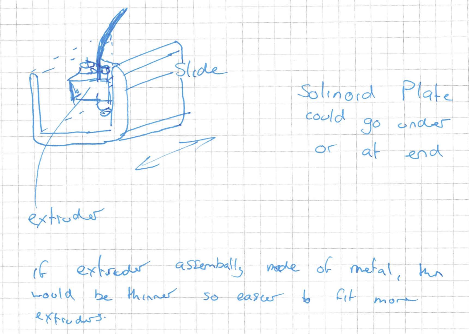
This was my first sketch and ideas page, hence why its quite messy. Most of the drawings, except for the one in the top left are of ways to try and make a mechanism that would allow multiple extruders to be used with a plate that would allow only one of these extruders to be operational, ie only allow one extruder to have a clear hole/access down to the work below. This is also the reason for the question in the top left, as if the plastic won't drip, we won't need such a mechanism and can just stop pushing the plastic or pull it back a bit to create a vacuum. These mechanisms would be operational with the use of solenoids or motors, both being expensive and hence why its better to try and avoid such mechanisms.


This drawing is purely about the tip/hot end on the extruder. The insulator bits show a large extrusion for the internal hole, but this need not be so big, just big enough so it sits in the case material. The question which I'm not sure if it will be readable on the uploaded image is asking what the size of the tip itself should be as a larger tip would have a larger heat capacity and thus not need as much energy to keep at the same temperature but its large, so would a smaller one but with less heat capacity be better. The other important thing on this page is the material for this insulator. I short listed a few which all have melting points supposedly higher but I'm not sure about expense, availability or the operating temperatures.
This last image is about the slide, simply showing potential of a U shaped slide.
The next thing I designed, was when I got back. I was looking over the 2012 in review post on the RichRap Blog and re-found the post on his paste extruder. I had originally decided this wasn't for me as it used a syringe which wouldn't hold enough paste to be useful but while having a few mates round for drinks, one of them came up with the idea of just using a syringe and then pumping or sucking more paste into the syringe. So once reminded of this post I had a look at how his syringe extruder worked and quickly realised the design he had used would not work for me as it would only work in one direction and thus would not be able to suck. (I think sucking will be better than pumping as it requires less parts and thus less expensive, plus if it doesn't work is much easier to convert to pump than it is to ignore sucking the first time round and then be stuck if pumping doesn't work.) So while trying to think of how to do this, I checked wikipedia for how to spell actuator (it was almost midnight and I was half asleep so I was trying to spell actuator like auxiliary with the start being aux and so couldn't get spell check to fix it.) One the wikipedia page, I saw screws could be used as a basic actuator (not that I didn't know this, it just wasn't at the forefront of my head at the time) and so realised this would be the best way to implement the actuator so it can move the syringe both up and down.

That is all of the ideas I have come up with over the last few days, but there were some others that I had written down to type up on the blog. Firstly I found a tutorial for SMD soldering using standard solder, a standard soldering iron and de-soldering wick. I thought it seemed like a good idea but the comments when I just checked now seem to indicate otherwise. It also sort of states the obvious but still something I had not thought about which was to use tweezers when handling SMD parts.
A few posts ago I had thought a camera would be nice to incorporate. I soon realised the camera modules were actually quite hard to find for some reason and seem to have to be ordered direct from the manufacturers. I have since found one from Little Bird Electronics.
Another thing I had thought of was to engrave each slide with the name its known by software, as this would make it far easier to debug and understand what settings were being changed etc. Talking of engraving, I've decided I would love a laser cutter! Within a week I had two completely non related people say I should get one with me having investigated them too that same week before anyone had said anything. They seem great, and would be great for cutting shapes out of wood, flat plastic and metals. This in conjunction with out press that can bend metal into shape would be great for making brackets and things like cases such as for the extruder above. One can only dream though.
And so to finish off this post, I'll say one last thing which I had realised when I was testing the stepper motors back in November. For something that makes mechanical/structural items, it has large amounts of electronics involved!