Showing posts with label Atmel AVR. Show all posts
Showing posts with label Atmel AVR. Show all posts
Thursday, February 7, 2013
Binary Buttons
This week I managed to get buttons working after lots of research for debouncing buttons. I went with hardware debouncing as was far easier to do. So this is a small circuit that takes input from four buttons and outputs them on a LCD as binary and decimal numbers. Here's a video of what I mean. My fingers are quite big compared to the PCB buttons so you can't really see me pressing the buttons.

Saturday, January 26, 2013
Stepper Demo and Serial LCD
I have finally got my Stepper motor demo program working. As well as the problems in the last post there were a couple others. The first one of these was that I was trying to add a signed integer to an unsigned one. I fixed this which then made me realise I would have to change the number of steps for reversing from -1 and -2 to 7 and 6 respectively. This wasn't so bad but I then found that the motor was going quite slow compared to the test program. This stumped me for a while until it came to me that unsigned 8bit integer, is just that 8 bit not 8 numbers in total (4bit). So I put in an if statement that stated if the counter position was greater than 7 to remove 8 from it so to get back into the correct range of 0-7. I won't post the code in this post as I still need to tidy it up and comment it. Here is another video of the stepper motor, this time running the demo code. Basically it moves 45 degrees forward, 45 degrees back, then flashes a light (not shown) and then starts alternating going backwards and forwards 360 degrees.
The video is slightly better quality today as I took this on my camera rather than my phone. Same goes with the pictures further down the post.
So after getting the stepper motor finally working, I decided I would start on the LCD display but this time using serial communication. This started fairly well and had a good example in the manual for the chip. There was also a tutorial on AVR Freaks that helped. So I wrote all this up and sent it to the microcontroller and it started writing to the screen, the only problem was that it wasn't writing what it should have. This looked like the next picture, which looks like asian symbols but I think are just normal symbols that are part of the extended ascii sequence.
 At I gave up programming and did some research before bed. I found another forum topic on AVR Freaks about UART corruption which is what I thought was happening. These posts indicated that it was most likely to do with the baud prescaller number calculated in the code. The next morning I tried moving around the number given in the manual for 8Mhz but no such luck. I had been seeming to get better results from lower numbers so I decided to try the number for 4Mhz which worked. I have no idea why it is running at 4Mhz as the fuses in AVR Studio say its running from a 8Mhz clock and not divided by 8 but there may be something I'm missing.
After fixing the communication I was finally able to turn on the back light of the LCD03-20x4. Next I managed to get some text written to the screen. With the help of this set of posts, again on AVR Freaks, I set up stdout for C to be the LCD screen and so printf now prints directly to the LCD.
 I'll post the code for what I have done with the screen below. I would do a circuit schematic but really its quite obvious for the ATmega88a as there is only one UART module and so there is only one TX and one RX pin on the chip. I'm also quite tired tonight after redoing the roof on part of our house (doing the same tomorrow), so can't think what else I was going to post.
The code really should be commented but I'm too tired to do so now and I'll most likely update and clean up the code soon so I can post it after that. Next job I'm thinking I'll do is to get SPI working between two chips. Before I do this though, I need to get the chip to run without the need for the programmer (AVR ISP mkII) being plugged in.
So after getting the stepper motor finally working, I decided I would start on the LCD display but this time using serial communication. This started fairly well and had a good example in the manual for the chip. There was also a tutorial on AVR Freaks that helped. So I wrote all this up and sent it to the microcontroller and it started writing to the screen, the only problem was that it wasn't writing what it should have. This looked like the next picture, which looks like asian symbols but I think are just normal symbols that are part of the extended ascii sequence.

After fixing the communication I was finally able to turn on the back light of the LCD03-20x4. Next I managed to get some text written to the screen. With the help of this set of posts, again on AVR Freaks, I set up stdout for C to be the LCD screen and so printf now prints directly to the LCD.

 #define BAUD_PRESCALE 51 // Started at 103 , down to 95, upto 112
 #define USART_LCD_MAXLINES 4
 #define USART_LCD_CHARS 20

 #include <avr/io.h>
 #include <util/delay.h>        // for _delay_ms()
 #include <stdio.h>
 #include <stdint.h>
 #include <ctype.h>

 void USART_Init (unsigned int ubrr)
 {
      /* baud rate */
      UBRR0H = (unsigned char) (ubrr>>8);
      UBRR0L = (unsigned char)ubrr;
      /* Enable receiver and transmitter */
      //UCSR0B = (1<<RXEN0)|(1<<TXEN0);
      UCSR0B = (1<<TXEN0);
      /* Set frame format: 8bit data, 2 stop bit */
      UCSR0C = (1<<USBS0)|(1<<UCSZ00)|(1<<UCSZ01);
 }

 void USART_Transmit (unsigned char data)
 {
      /* Wait for empty transmit buffer */
      while (!(UCSR0A & (1<<UDRE0)))
           ;
      /* Put data into buffer, sends the data */
      UDR0 = data;
 }
 int USART_PrintChar (char character, FILE *stream)
 {
      USART_Transmit (character);
      return 0;
 }
 FILE uart_str = FDEV_SETUP_STREAM(USART_PrintChar, NULL, _FDEV_SETUP_RW);

 void USART_Print_Location(uint8_t line, uint8_t pos) {
      if ((line < 1) || (line > USART_LCD_MAXLINES)) {
           line = 1;
      }
      if ((pos < 1) || (pos > USART_LCD_CHARS)) {
           pos = 1;
      }
      USART_Transmit(3);
      USART_Transmit(line);
      USART_Transmit(pos);
 }

 int main(void)
 {
      USART_Init(BAUD_PRESCALE);
      stdout = &uart_str;
      unsigned char sendChar = 65;
      USART_Transmit(19);
      USART_Transmit(12);
      USART_Print_Location(1,5);
      printf("Hello World");
      USART_Print_Location(2,9);
      printf("from");
      USART_Print_Location(3,1);
      printf("RichRobo on Blogger");
      while(1)
   {
     //TODO:: Please write your application code
   }
 }
The code really should be commented but I'm too tired to do so now and I'll most likely update and clean up the code soon so I can post it after that. Next job I'm thinking I'll do is to get SPI working between two chips. Before I do this though, I need to get the chip to run without the need for the programmer (AVR ISP mkII) being plugged in.
Tuesday, January 22, 2013
Stepper Motor Setup
Well after getting my stepper motor to work last night with full steps, today I got it to work with half steps and so wrote up the circuit and the major problem I had encountered.
Firstly here is another video of the stepper, this time running at a decent speed, using half steps.
You can't tell from the video, but the motor does run much smoother with half steps as well as being able to run faster (logical if you think about how charging the coils works).
So I'll give the schematic next to show you the circuit layout, then I'll go into the problem I had and finally the code. The schematic does look messy, I would fix this by labelling the wires but I found out tonight that KiCAD doesn't have this functionality so it will have to do.
 In the test program shown working in the video, the LEDs in the bottom right seem like they are on all the time but they are actually connected to each coil of the stepper and so turn on when that coil is on in that direction. This was so I could work out what was happening and can easily be removed. I will go into why they were useful in a second. Other things to note are that the switches on the left are attached but not used in this test program as these were for my original demo program which I will get working soon and so can do more tests. In the video there is a SMD chip on a red board. This is not actually attached to the circuit at the moment. This is because it is the other stepper driver chip (A3982SLB-T) which I will test later when I have a better heat sink for it than the tiny one I bought at the time which doesn't fully cover it.
OK, so my problem for why the stepper wasn't working was quite trivial in the end. It turned out that I had connected the stepper in a non standard way and so the guides on programming for a stepper motor didn't work.
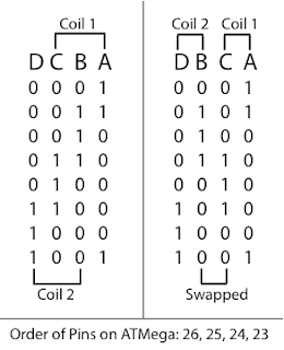 Basically the standard order is connecting the coils in alphabetic order as shown in their data sheets. This means that the coils are intertwined as shown on the left of the above picture. This wasn't how I connected them as it seemed more logical to me to attach them so the coils were attached next to each other as shown on the right. As a side note, the letters in the picture are the letters from the data sheet, the numbers are the logical output of the pins on the pins of the microcontroller, and so when in the wrong order do weird things. This meant that instead of moving, the stepper oscillated between two locations while the rest of the time, the potential difference (voltage) over the coil was zero (ie both off or both on). What I realised from testing with the help of the LEDs connected and using a slower clock speed was that I had one coil with both sides on logical 1 and the other coil on logical 0 most of the time hence why it was not working. So once I swapped the two middle columns of the logical states in the table above, it all magically started working. This was something I had not read in any of the tutorials online or in text books to be careful of so I'm quite happy that I managed to solve this for myself.
So here is my code:
(Note to self, using http://codeformatter.blogspot.com/ with settings 5 spaces per tab, no line numbering, don't remove blank lines, yes to stylesheet, auto height and no to alternative background)
Its fairly rudimentary at the moment and needs tidying up but it shows the gist. I used decimals as it was easier to test and write down than using binary numbers which I had used in my demo which wasn't working. For those interested, binary in GCC and Atmel Studio can be written down using 0b as a prefix to the binary string. The code above won't work straight from copying as I have commented out the method for changing between full steps and half steps. The other thing to note is that my chip is running at 4Mhz so the time would need to be changed if running at a slower speed.
I think that is all about getting the stepper working. Tomorrow I'll either fix it up for use with my demo program which turns certain amounts and then gives control to the buttons, or I'll have a go with serial communication to the LCD screen. I might if I have enough time, have a look at both.
Just to finish off, I was looking around Australian Robotics this afternoon and found there is a ball bearing on there which is 5mm thick with an ID of 5mm and OD of 16mm. This could potentially work for wheels on the carriage but after realising that the motor shaft is also 5mm diameter and is quite large realistically, I think a smaller shaft diameter would make more sense. The same website also has a coupler for converting the 5mm diameter shaft of the motor to 8mm which would work well for M8 threaded rod or an 8mm ball screw.
I'll should have enough stuff to post again by tomorrow night or the night after as will be at home working on it for the next few days. Should be good.
Firstly here is another video of the stepper, this time running at a decent speed, using half steps.
So I'll give the schematic next to show you the circuit layout, then I'll go into the problem I had and finally the code. The schematic does look messy, I would fix this by labelling the wires but I found out tonight that KiCAD doesn't have this functionality so it will have to do.

OK, so my problem for why the stepper wasn't working was quite trivial in the end. It turned out that I had connected the stepper in a non standard way and so the guides on programming for a stepper motor didn't work.

So here is my code:
 #include <avr/io.h>
 #include <util/delay.h>        // for _delay_ms()

 int main(void)
 {
   DDRC |= 0x0F;

      uint8_t curLED = 1;
      while (1) {
           PORTC = curLED;
           _delay_ms(7); // 18 for full steps, 7 for half steps

           /** Full Steps **
           if (curLED == 1) {
                curLED = 4;
           }
           else if (curLED == 4) {
                curLED = 2;
           }
           else if (curLED == 2) {
                curLED = 8;
           }
           else {
                curLED = 1;
           }
           **/
           /** Half Step **
           if (curLED == 1) {
                curLED = 5;
           }
           else if (curLED == 5) {
                curLED = 4;
           }
           else if (curLED == 4) {
                curLED = 6;
           }
           else if (curLED == 6) {
                curLED = 2;
           }
           else if (curLED == 2) {
                curLED = 10;
           }
           else if (curLED == 10) {
                curLED = 8;
           }
           else if (curLED == 8) {
                curLED = 9;
           }
           else {
                curLED = 1;
           }
           */
   }
   return 1;
 }
(Note to self, using http://codeformatter.blogspot.com/ with settings 5 spaces per tab, no line numbering, don't remove blank lines, yes to stylesheet, auto height and no to alternative background)
Its fairly rudimentary at the moment and needs tidying up but it shows the gist. I used decimals as it was easier to test and write down than using binary numbers which I had used in my demo which wasn't working. For those interested, binary in GCC and Atmel Studio can be written down using 0b as a prefix to the binary string. The code above won't work straight from copying as I have commented out the method for changing between full steps and half steps. The other thing to note is that my chip is running at 4Mhz so the time would need to be changed if running at a slower speed.
I think that is all about getting the stepper working. Tomorrow I'll either fix it up for use with my demo program which turns certain amounts and then gives control to the buttons, or I'll have a go with serial communication to the LCD screen. I might if I have enough time, have a look at both.
Just to finish off, I was looking around Australian Robotics this afternoon and found there is a ball bearing on there which is 5mm thick with an ID of 5mm and OD of 16mm. This could potentially work for wheels on the carriage but after realising that the motor shaft is also 5mm diameter and is quite large realistically, I think a smaller shaft diameter would make more sense. The same website also has a coupler for converting the 5mm diameter shaft of the motor to 8mm which would work well for M8 threaded rod or an 8mm ball screw.
I'll should have enough stuff to post again by tomorrow night or the night after as will be at home working on it for the next few days. Should be good.
Monday, January 21, 2013
Stepper Motor Full Step
Very quick post, but tonight I decided I would write a small test program to manage the stepper motor now that I can see which coils are on using LEDs. I was successful in getting the motor to turn which is good as it means the wiring is all correct and it must be my original program that does not work. I'll have a better look into this in the next few days.
This test program, as my first test has very large waiting periods between changing step so the motor does go quite slow. The other thing to note for the test program I'm using is that it is using full steps rather than half or smaller. This is simply because I'm testing and was my first go. I'll do a proper write up later about the circuit and setup but for the time being I have a video showing it moving, as I'm quite happy I've managed to get it working even though its a minor achievement.
This test program, as my first test has very large waiting periods between changing step so the motor does go quite slow. The other thing to note for the test program I'm using is that it is using full steps rather than half or smaller. This is simply because I'm testing and was my first go. I'll do a proper write up later about the circuit and setup but for the time being I have a video showing it moving, as I'm quite happy I've managed to get it working even though its a minor achievement.
Sunday, January 20, 2013
Major Design Change again...
I've been trying to write this post for the last five days but have been unable to find time due to work and chores round the house. So first things first, I did manage to draw a reasonably accurate illustration of the design. It helped me think of a few things I hadn't thought of yet such as the X slide motor on the I beam would need to be mounted on a plate from the front so it doesn't dragged across the angle material of the Y slide. After this point though I basically abandoned finishing the drawing. This was because I felt the canter-leaver of the X slide would be hard to secure onto the Y slide. This joint is shown with a circle, in the picture below.
 To over come this I had a small brainstorming. During this I found there was a new MendelMax (version 2). This gave me some good ideas. I wanted to still use the carriage design as I thought the current design worked quite well (more later on in this post about the carriage), so this would need to be kept in mind.
I then came up with a design fairly similar to the MendelMax version 2 above and mixed with a wharf/cargo crane.
 When I first drew this design out I thought it would be great if the whole frame could move above the work as this would save on the footprint of the printer and so save space. (This was sort of one of my aims - to have the printer so it would fit on a desk, with my desk being 600mm deep so hopefully able to fit on that with out encroaching over the edge.) I might have to abandon the frame moving idea but I'm not sure. I can use the aluminium extrusion bars mentioned in relation to the very first design, for tracks for instance but I have not evaluated this yet. The other option is to design it like the MendelMax with the work moving for one of the directions. This might seem like a back flip for my ideas, and in a way it is but all in all, the project is a learning one so its no surprise that I end up with a design similar to others. I could make sure the sliding frame would work if I didn't use aluminium and used steel for example instead but I would prefer it to be light enough to move if needed which steel would parts would not help with.
In this design the slide between the two sides could be the carriage design and the Z slide could be the same again or just use track like the bottom. I had also when first thinking of this design, to not bother with diagonals for the uprights but after looking at the MendelMax2 I thought this would be a better idea.
I then started designing the carriage that I think is a good idea in Inventor. I haven't finished it yet but here are some pictures showing my ideas. I also haven't finalised on dimensions or locations so some parts are out of place. The four wheels that roll along the centre part of the I beam will have holes cut into the rectangular hollow so they have enough room to spin while also allowing the material to protrude in enough that the wheels in the upright position have somewhere to mount on both sides.


 The diagrams above also have a very key part missing, that is the mechanism that joins the wheels to the aluminium. I'll attach them as shown in the following image.


I then came up with a design fairly similar to the MendelMax version 2 above and mixed with a wharf/cargo crane.

In this design the slide between the two sides could be the carriage design and the Z slide could be the same again or just use track like the bottom. I had also when first thinking of this design, to not bother with diagonals for the uprights but after looking at the MendelMax2 I thought this would be a better idea.
I then started designing the carriage that I think is a good idea in Inventor. I haven't finished it yet but here are some pictures showing my ideas. I also haven't finalised on dimensions or locations so some parts are out of place. The four wheels that roll along the centre part of the I beam will have holes cut into the rectangular hollow so they have enough room to spin while also allowing the material to protrude in enough that the wheels in the upright position have somewhere to mount on both sides.


This is a change from what I had previously designed. This is due to the previous design only being attached in one place and at 90 degrees so if there managed to be forces in the wrong location is was much more prone to damage.
Recently while trying to think of other uses for the printer I've worked out I could potentially use the printer for CNC drilling which would be great for doing circuit boards. Out of this same idea I thought the extruders could also be used for solder as it runs about the same temperature as PLA.
I've now gone back to having a look at the electronics. I've had a quick look at the stepper motor driver. I've attached some LEDs to each of the leads. This means that if neither LED is on for a coil then its off, same when both are on and if only one of the two for each coil is on then it should be positive or negative 12V. At the moment though it seems to have both on for one coil and both off for the second coil and hence why the motor does not spin. I'll write a test program that turns on each pin separately on the ATMega and see of I can get it to go to each state. If this doesn't work I'll have a look at the wiring and maybe redo it. If this still doesn't work, I managed to solder the SMD stepper controller on Friday with just a normal soldering iron and so can try that out.
With regards to the display, I'm going to try the serial connection which I said before. This looks to be much easier than I2C but does mean I can't use serial for anything else. This isn't such a concern as I can use SPI for connecting the controllers together.
This next week I have more time to work on the project as I'm not at work for two full days so should be able to spend more time on it as it seems like ages since I did anything even though its only been 4 or 5 days.
Saturday, October 27, 2012
Electronics update
I've realised I can't do much more on the structural side of the printer until I start properly designing it in inventor which takes far more time than I'm willing to use for procrastination. So in the mean time all posts will be electrical based.
So, I've managed to get my ATmega88A chip up and running. I managed to get the programmer (AVRISP2 MKII) working with the Mac, by changing drivers. The original drivers weren't picking up the device. I found the method for the fix the problem at http://cooperlees.com/blog/?p=414. I used the osx-pl2303 driver as it had more entries to change than the standard prolific driver (I tried adding an entry to both but failed both times so had to edit a previous one). In hindsight I probably should have used the official or some other driver as the osx-pl2303 drivers use a weird naming convention for the file system sockets. It also doesn't support OSX 10.7 or 10.8 for future use. I didn't use USBProber as the article said and simply used the values from system profiler above which I then converted to decimal (with the help of Google, I was being lazy). With this I thought great, I should be able to program now from the mac using CrossPack (avr-gcc, avr-dude etc), unfortunately no such luck. I haven't had a lightbulb moment since fixing the driver issue so I've resorted to programming mainly on XCode and then copying the files to AVR Studio on Windows to download and debug. To actually set up the connection to the chip, I had to create an adaptor that went from the 3x2 connector on the MKII to a spread out version that would fit into the bread board. Sorry about the colours of the different pictures being bad but I couldn't be bothered using a proper camera and my phone wasn't picking up great colours with the incandescent room light (flash and the desk fluorescent over exposed the pictures). The adaptor is made using header pins and variboard. So to not short between the two sides of the connector, a knife was used to cut the track. I also used a knife to cut and break the variboard, but looking back I should have used a band saw (though most people won't have one of these).
That is all I have done so far with the setting up the programming, I'm going to write another post after this about controlling the brightness of a LED using PWM. I've realised this morning that PWM might not be as useful as I had hoped for this project as its continuous, and instead might be controlling the steppers purely with on and off signals to the pins. PWM could be used for the pump or the extruders as they won't need to be as accurately driven.
In other news, I can't use the Freeflex heated tubing I was hoping to use as they only supply to OEMs in large quantities. This means I'll have to make my own heated tubing or abandon the idea altogether and hope it doesn't harden in the tube. I don't want to use a syringe as that would mean not being able to do large chocolate items. I had a look into header fittings (for connecting the slave controllers to the master) and found out on the molex site that they should be able to cope with 2-3A depending on the wire sizes (here and here). This means I should be able to simply use header connections to connect the motors and slave controllers to the main electronics. I also was thinking last night that I might include a global interrupt wire that can be pulled high or low (not sure yet) when there is an error. This would cause everything to stop and remember where it was up to while the master controller checked with each component for errors. The reason for this is that if something goes wrong, say one motor out of two in the Z slide stops working, the controller can stop everything and correct or signal to the user so something else doesn't break or become damaged.
That's all for this post. I'll write another quick post about setting up the ATmega88A to control a LED brightness. The reason for keeping these separate is so its easier to search and if someone just wants to know about that and not the rest of the 3D printer stuff they aren't given unnecessary information.
So, I've managed to get my ATmega88A chip up and running. I managed to get the programmer (AVRISP2 MKII) working with the Mac, by changing drivers. The original drivers weren't picking up the device. I found the method for the fix the problem at http://cooperlees.com/blog/?p=414. I used the osx-pl2303 driver as it had more entries to change than the standard prolific driver (I tried adding an entry to both but failed both times so had to edit a previous one). In hindsight I probably should have used the official or some other driver as the osx-pl2303 drivers use a weird naming convention for the file system sockets. It also doesn't support OSX 10.7 or 10.8 for future use. I didn't use USBProber as the article said and simply used the values from system profiler above which I then converted to decimal (with the help of Google, I was being lazy). With this I thought great, I should be able to program now from the mac using CrossPack (avr-gcc, avr-dude etc), unfortunately no such luck. I haven't had a lightbulb moment since fixing the driver issue so I've resorted to programming mainly on XCode and then copying the files to AVR Studio on Windows to download and debug. To actually set up the connection to the chip, I had to create an adaptor that went from the 3x2 connector on the MKII to a spread out version that would fit into the bread board. Sorry about the colours of the different pictures being bad but I couldn't be bothered using a proper camera and my phone wasn't picking up great colours with the incandescent room light (flash and the desk fluorescent over exposed the pictures). The adaptor is made using header pins and variboard. So to not short between the two sides of the connector, a knife was used to cut the track. I also used a knife to cut and break the variboard, but looking back I should have used a band saw (though most people won't have one of these).
 | ||
| The breadboard programming adaptor |
In other news, I can't use the Freeflex heated tubing I was hoping to use as they only supply to OEMs in large quantities. This means I'll have to make my own heated tubing or abandon the idea altogether and hope it doesn't harden in the tube. I don't want to use a syringe as that would mean not being able to do large chocolate items. I had a look into header fittings (for connecting the slave controllers to the master) and found out on the molex site that they should be able to cope with 2-3A depending on the wire sizes (here and here). This means I should be able to simply use header connections to connect the motors and slave controllers to the main electronics. I also was thinking last night that I might include a global interrupt wire that can be pulled high or low (not sure yet) when there is an error. This would cause everything to stop and remember where it was up to while the master controller checked with each component for errors. The reason for this is that if something goes wrong, say one motor out of two in the Z slide stops working, the controller can stop everything and correct or signal to the user so something else doesn't break or become damaged.
That's all for this post. I'll write another quick post about setting up the ATmega88A to control a LED brightness. The reason for keeping these separate is so its easier to search and if someone just wants to know about that and not the rest of the 3D printer stuff they aren't given unnecessary information.
Sunday, October 21, 2012
Update on yesterday's design change
Overnight I was thinking on how to improve on the design of yesterday (my mind seems to wander onto this project a lot!) and thought the second idea was pretty good. I decided that with the duel supports for the head/extruder I wouldn't need to move the bed up and down. So I moved the Z slide control/ball screws onto the Y slide. At the same time I was thinking about the placements of the motors and realised that I have to put the X slide motor on top so the ball screw and motor don't get in the way of objects below. This then meant that the Y slide motor and ball screw could go on the underneath of the Y slide which would be very neat. The Z motor and ball screw in the picture is shown only one one side but I would put it on both sides I just couldn't be bothered drawing it on both. The 'M's in the picture are motors and the 'H' is the head or the the mount for the extruder.
 I'm quite happy with design and I think as long as the join there the X slide connects to the Y slide is strong enough it will be a great design that is much more space saving than the other design. I think I will order some stepper motors this coming week so I gauge the weight then I can do some calculations on the strength of the joint after my exams (that really will be after exams as that will take some time to do not just thinking). I'm still going to try and use aluminium for the structure as its lightweight (no one really wants a 10-30KG object on their desk!)
In other news I've got my ATmega chips and programmer (mkII). I'll post some stuff about it soon. I've got it all working under windows on my laptop (I was strangely happy when I got a LED flashing) but haven't managed to get the mkII to come up as a device on OSX and thus can't do much on OSX itself, so I'll keep trying to work that out.

In other news I've got my ATmega chips and programmer (mkII). I'll post some stuff about it soon. I've got it all working under windows on my laptop (I was strangely happy when I got a LED flashing) but haven't managed to get the mkII to come up as a device on OSX and thus can't do much on OSX itself, so I'll keep trying to work that out.
Sunday, October 14, 2012
ATmega series microcontroller for 3D printer
I'm going to start investing some money into this project. I went scouring the web to understand how the ATmega series worked, how to program them and if said programming could be done with open source software like GCC. This post shows the steps I took though I didn't actually do them in this order as I sort of stumbled round trying to work out what to do.
I choose the ATmega series of Atmel chips because it seems very popular - it has lots of people using them for a very large range of projects and my mate uses them so I could get help if I needed. The first step was to find what all the different numbers at the end of the ATmega name meant. I found out that this is mostly to do with memory, such as they have 8k, 16k, 32k, 64k and 128k flash. The numbers and letters after those were for features such as numbers of channels for ADC (analog to digital converter), PWM (pulse width modulation) and DAC (digital to analog Converter) for example. I also had a look at other AVR chips that were SMD based and found the AT90PWM2B model that has 9 channels for PWM which would be great for doing some of the slave controllers. SMD for the production model would be great as although not use to reuse, it reduces the size of the PCB phenomenally. The 9 PWM channels would be great for the extruder and Z slide controller due to the number of steppers (each requiring two PWM channels). There was also AT90PWM3B which had 11 PWM channels.
I next went looking for a programmer. My TI LaunchPad MSP430, had a development board that I used to program so I thought this was the easiest thing to use. I had a look round and I couldn't find anything similar, all I could find was very feature rich (but useless features for my case) development boards and they tended to be very expensive. I decided there must be an easier way to program, so contacted my friend and he referred to me the AVAVRISP2 or mkII. This allows programming by a six pin header connected to the chip. This was very different to the MSP-EXP430G2 board I had used previously.
I next looked at programming tools. The AVR software is free for windows so I will install that under windows but most of my time is spent in Mac OS and occasionally in linux. This meant I had to find another solution which came in the form of avr-gcc, avr-libc and avrdude. These are all open source and based on the equivalent for linux except for avrdude which is the downloader that is specially designed for AVR chips which encompass the ATmega chips.
After this I was feeling quite enthused and went looking for some advanced designed people had used and found that people had managed to get SD cards and network (with IPv6) to work. Once such project is the ethersex project. This has all sorts of functionality including SD cards, IPv6, screen controller and an HTTP server which would be a great was of sending data to the printer.
So some time this week I'll order some ATmega88A-PU chips, the AVAVRISP2, another breadboard (I have one but its my dad's) and I'll get some header strip so I can interface the AVAVRISP2 to the breadboard. My first project on the chip will be to get the LCD display working and then I'll move on to stepper motor controllers (where I'll use this stepper motor which I referenced in a previous post). Hopefully should all be much easier than the cheaper but very much worse quality MSP430 I have. That is all I have to say on the electronics for now, I have some ideas for the mechanical and structural side of things but that can wait for another post.
I choose the ATmega series of Atmel chips because it seems very popular - it has lots of people using them for a very large range of projects and my mate uses them so I could get help if I needed. The first step was to find what all the different numbers at the end of the ATmega name meant. I found out that this is mostly to do with memory, such as they have 8k, 16k, 32k, 64k and 128k flash. The numbers and letters after those were for features such as numbers of channels for ADC (analog to digital converter), PWM (pulse width modulation) and DAC (digital to analog Converter) for example. I also had a look at other AVR chips that were SMD based and found the AT90PWM2B model that has 9 channels for PWM which would be great for doing some of the slave controllers. SMD for the production model would be great as although not use to reuse, it reduces the size of the PCB phenomenally. The 9 PWM channels would be great for the extruder and Z slide controller due to the number of steppers (each requiring two PWM channels). There was also AT90PWM3B which had 11 PWM channels.
I next went looking for a programmer. My TI LaunchPad MSP430, had a development board that I used to program so I thought this was the easiest thing to use. I had a look round and I couldn't find anything similar, all I could find was very feature rich (but useless features for my case) development boards and they tended to be very expensive. I decided there must be an easier way to program, so contacted my friend and he referred to me the AVAVRISP2 or mkII. This allows programming by a six pin header connected to the chip. This was very different to the MSP-EXP430G2 board I had used previously.
I next looked at programming tools. The AVR software is free for windows so I will install that under windows but most of my time is spent in Mac OS and occasionally in linux. This meant I had to find another solution which came in the form of avr-gcc, avr-libc and avrdude. These are all open source and based on the equivalent for linux except for avrdude which is the downloader that is specially designed for AVR chips which encompass the ATmega chips.
After this I was feeling quite enthused and went looking for some advanced designed people had used and found that people had managed to get SD cards and network (with IPv6) to work. Once such project is the ethersex project. This has all sorts of functionality including SD cards, IPv6, screen controller and an HTTP server which would be a great was of sending data to the printer.
So some time this week I'll order some ATmega88A-PU chips, the AVAVRISP2, another breadboard (I have one but its my dad's) and I'll get some header strip so I can interface the AVAVRISP2 to the breadboard. My first project on the chip will be to get the LCD display working and then I'll move on to stepper motor controllers (where I'll use this stepper motor which I referenced in a previous post). Hopefully should all be much easier than the cheaper but very much worse quality MSP430 I have. That is all I have to say on the electronics for now, I have some ideas for the mechanical and structural side of things but that can wait for another post.
Saturday, October 13, 2012
Extruders, heaters and more
Another day another post. So I was waiting to ask someone a question at uni today so last night and today I've done a heap of research, which I've put into sections (sort of) to try and make sense.
So firstly, in the last post I was talking about whether to use slave controllers. Well I realised today on the bus, that the slave controller idea would also be far better for the extruder controller. This is because it would be far easier to upgrade that with more pins for more functions such as multiple extenders, sensors and fans compared to constantly upgrading the master controller. It also as I think I mentioned last time could do errors and monitoring to stop annoyances such as this (which as is stated at the end of the page, was caused by poor quality filament). Talking of which I found a blog for an electrical engineer in the UK who has been playing round with a MendelMax also so I got some ideas of there. The site is http://richrap.blogspot.com/. Staying with controllers, I've decided I'll go for the ATMega micro controllers for the slave controllers. They seem to work well, my mate has one and loves it, and my current MSP430 chips are annoying me to death. I've been trying to fix a problem (even directly used their sample code and wouldn't work) with one for over two weeks and still isn't working. So I've decided to give up on the MSP430 side of things for now, I'm sure other chips in the family work but the two I'm using from the G2XXX family are rubbish. I decided I also wouldn't use a PIC as it didn't support GCC which is what I would prefer to use for development as it is available on multiple platforms (I use Mac OS X, Windows 7 and XP and multiple variants of Linux).
Now for some heating. I decided early on I would prefer a sort of climate control, as in a heater to keep the ambient temperature constant and then fans to extract heat when necessary. The bed and extruder would be within an enclosure to keep the temperature constant also by reducing convection. So looking into it I found that the best type of base heater is a PCB type, basically small wires on a PCB with excess current being pushed through so it heats up. This is elegant but can be expensive if the boards are professionally made. (Reference: http://reprap.org/wiki/Heated_Bed). I think this is the best option still and can be made to have etched warnings on the other side of the PCB. The RepRap has a 300x300mm PCB heater but this is really a tad on the small size for what I would like. I also think that a glass top would be the best for the base of the work area so to spread the heat more evenly. In this post it is recommended that a mirror could be used instead as it had better evenness in the heat. A page on the UltiMaker site said that sheet metal was better than glass at evenness by a magnitude of 27 times. This is relative to pure glass though and since mirrors have a thin metallic layer, I think the mirror would work better as sheet metal has sticking problems, gets scratched and hence has to be replaced every so often. The same site also mentioned how ventilation and fans can cause localised cooling on the head bed and some of the effects. I think I would incorporate two fans one for blowing air in and the other air out. This though is just thoughts and I haven't analysed the best practises here as this is more of a feature than something that is required to print.
Moving onto items of a building nature, I think the electronics should be placed underneath the heating bed. There would obviously need to be insulation between the bed and the electronics so to not cool the electronics but I think its the best place for it. I initially had thought to make one of the walls contain all the electronics but have since decided that it would be nice if all four sides were clear with perspects or glass (perspects might melt I realised so might have to be glass). All the joints for holding things together should also be aluminium in this design as firstly I don't have a 3D printer to print plastic parts and secondly its still lightweight, cheapish and looks great.
Now something a tad more interesting and very central to the printer, the extruder or jet as I might occasionally call it. Firstly there are lots of designs and the background on simple extruder's on the RepRap site here. I will use this basic design for the plastic side of the extrusion. Qu-Bd came up with a simple idea for making the filament stay in the middle of the gearing that pushes it through so to make sure it won't mass a beat. This is done, quite simply by having the middle of the gear curved. As I've said before I want to be able to have multiple extenders so to I can get different colours during a build. So tonight I had a look round at different systems for stopping fluids. I had envisioned a pneumatic system that sort of sucked up the fluid if it needed to stop quickly but I soon realised this was complex and maybe not even practical. I kept looking round and eventually realised that in essence it was just a valve I needed. So I found three types of valves that might be useful, diaphragm, pinch and knife. The first two are two complex and expensive to use so a simple and fast moving knife valve should do the trick. The design I'll use will be slightly different from a conventional knife valve though as it needs to be able to fast move. This shouldn't be a problem though as the area that the valve will be acting on will be quite small. Just for reference on one way of mounting a three way extruder, (though this one does not use valves to stop drips) here is one from the blog I have referenced prior.
Now here is something exciting, the chocolate extruder! Firstly this extruder will have to be separate from the plastics one above due to cleanliness and safety. This means that the carriage that holds the extenders will be made for quick changes. I've decided that I'll use a separate device to get the chocolate into the correct state. This can be controlled by the master controller but has to be separate as to keep aesthetics as well as weight considerations on the structure. Due to this I've realised I should be able to pump the molten chocolate through a heated tube similar to this Freeflex Heated Tubeing straight to the jet to print. This is lightweight and means it easier to keep a constant supply of chocolate on the go for large models. With chocolate, I've found out that there is different phases or types of chocolate and that one of these is particularly favourable. This is due to the higher strength, higher melting point and crunch of the phase. This means that chocolate should be heated up to approximately 40 degrees, given time to cool then heated to between 27.3 and 33.8 so phase IV will melt but phase V (the desired phase) won't then its ready to be printed. If there are impurities such as milk in the chocolate the temperature range decreases.
So with all that in mind, I think after exams I will buy an ATmega development board, get it working with my LCD I2C screen (I2C is the thing that just won't work on my MSP430) and then buy a stepper motor and make a driver up for it. Then if that goes well I can start designing more of the electronics. On the structural side, I need to work out how rigid everything needs to be and start formalising my designs by constructing them in inventor rather than my mind.
So firstly, in the last post I was talking about whether to use slave controllers. Well I realised today on the bus, that the slave controller idea would also be far better for the extruder controller. This is because it would be far easier to upgrade that with more pins for more functions such as multiple extenders, sensors and fans compared to constantly upgrading the master controller. It also as I think I mentioned last time could do errors and monitoring to stop annoyances such as this (which as is stated at the end of the page, was caused by poor quality filament). Talking of which I found a blog for an electrical engineer in the UK who has been playing round with a MendelMax also so I got some ideas of there. The site is http://richrap.blogspot.com/. Staying with controllers, I've decided I'll go for the ATMega micro controllers for the slave controllers. They seem to work well, my mate has one and loves it, and my current MSP430 chips are annoying me to death. I've been trying to fix a problem (even directly used their sample code and wouldn't work) with one for over two weeks and still isn't working. So I've decided to give up on the MSP430 side of things for now, I'm sure other chips in the family work but the two I'm using from the G2XXX family are rubbish. I decided I also wouldn't use a PIC as it didn't support GCC which is what I would prefer to use for development as it is available on multiple platforms (I use Mac OS X, Windows 7 and XP and multiple variants of Linux).
Now for some heating. I decided early on I would prefer a sort of climate control, as in a heater to keep the ambient temperature constant and then fans to extract heat when necessary. The bed and extruder would be within an enclosure to keep the temperature constant also by reducing convection. So looking into it I found that the best type of base heater is a PCB type, basically small wires on a PCB with excess current being pushed through so it heats up. This is elegant but can be expensive if the boards are professionally made. (Reference: http://reprap.org/wiki/Heated_Bed). I think this is the best option still and can be made to have etched warnings on the other side of the PCB. The RepRap has a 300x300mm PCB heater but this is really a tad on the small size for what I would like. I also think that a glass top would be the best for the base of the work area so to spread the heat more evenly. In this post it is recommended that a mirror could be used instead as it had better evenness in the heat. A page on the UltiMaker site said that sheet metal was better than glass at evenness by a magnitude of 27 times. This is relative to pure glass though and since mirrors have a thin metallic layer, I think the mirror would work better as sheet metal has sticking problems, gets scratched and hence has to be replaced every so often. The same site also mentioned how ventilation and fans can cause localised cooling on the head bed and some of the effects. I think I would incorporate two fans one for blowing air in and the other air out. This though is just thoughts and I haven't analysed the best practises here as this is more of a feature than something that is required to print.
Moving onto items of a building nature, I think the electronics should be placed underneath the heating bed. There would obviously need to be insulation between the bed and the electronics so to not cool the electronics but I think its the best place for it. I initially had thought to make one of the walls contain all the electronics but have since decided that it would be nice if all four sides were clear with perspects or glass (perspects might melt I realised so might have to be glass). All the joints for holding things together should also be aluminium in this design as firstly I don't have a 3D printer to print plastic parts and secondly its still lightweight, cheapish and looks great.
Now something a tad more interesting and very central to the printer, the extruder or jet as I might occasionally call it. Firstly there are lots of designs and the background on simple extruder's on the RepRap site here. I will use this basic design for the plastic side of the extrusion. Qu-Bd came up with a simple idea for making the filament stay in the middle of the gearing that pushes it through so to make sure it won't mass a beat. This is done, quite simply by having the middle of the gear curved. As I've said before I want to be able to have multiple extenders so to I can get different colours during a build. So tonight I had a look round at different systems for stopping fluids. I had envisioned a pneumatic system that sort of sucked up the fluid if it needed to stop quickly but I soon realised this was complex and maybe not even practical. I kept looking round and eventually realised that in essence it was just a valve I needed. So I found three types of valves that might be useful, diaphragm, pinch and knife. The first two are two complex and expensive to use so a simple and fast moving knife valve should do the trick. The design I'll use will be slightly different from a conventional knife valve though as it needs to be able to fast move. This shouldn't be a problem though as the area that the valve will be acting on will be quite small. Just for reference on one way of mounting a three way extruder, (though this one does not use valves to stop drips) here is one from the blog I have referenced prior.
Now here is something exciting, the chocolate extruder! Firstly this extruder will have to be separate from the plastics one above due to cleanliness and safety. This means that the carriage that holds the extenders will be made for quick changes. I've decided that I'll use a separate device to get the chocolate into the correct state. This can be controlled by the master controller but has to be separate as to keep aesthetics as well as weight considerations on the structure. Due to this I've realised I should be able to pump the molten chocolate through a heated tube similar to this Freeflex Heated Tubeing straight to the jet to print. This is lightweight and means it easier to keep a constant supply of chocolate on the go for large models. With chocolate, I've found out that there is different phases or types of chocolate and that one of these is particularly favourable. This is due to the higher strength, higher melting point and crunch of the phase. This means that chocolate should be heated up to approximately 40 degrees, given time to cool then heated to between 27.3 and 33.8 so phase IV will melt but phase V (the desired phase) won't then its ready to be printed. If there are impurities such as milk in the chocolate the temperature range decreases.
So with all that in mind, I think after exams I will buy an ATmega development board, get it working with my LCD I2C screen (I2C is the thing that just won't work on my MSP430) and then buy a stepper motor and make a driver up for it. Then if that goes well I can start designing more of the electronics. On the structural side, I need to work out how rigid everything needs to be and start formalising my designs by constructing them in inventor rather than my mind.
Subscribe to:
Posts (Atom)